4 receiving text data, Format of received data and data memory addresses, Kv -300 – KEYENCE Visual KV Series User Manual
Page 322
7.7 Non-procedure Mode Programming
KV-300 Series Only
KV
-300
KV-10/80
Chapter 7 KV-L2 Serial Interface Module
1-298
7
7.7.4
Receiving Text Data
This section describes reception of text data in non-procedure mode. The KV-L2
fetches text data from an external unit into the KV-300 CPU’s data memory.
Format of received data and data memory addresses
Text data of up to 100 bytes separated by the delimiter CR or CR LF can be written
into the assigned data memory addresses, one byte per data memory address, in
ASCII.
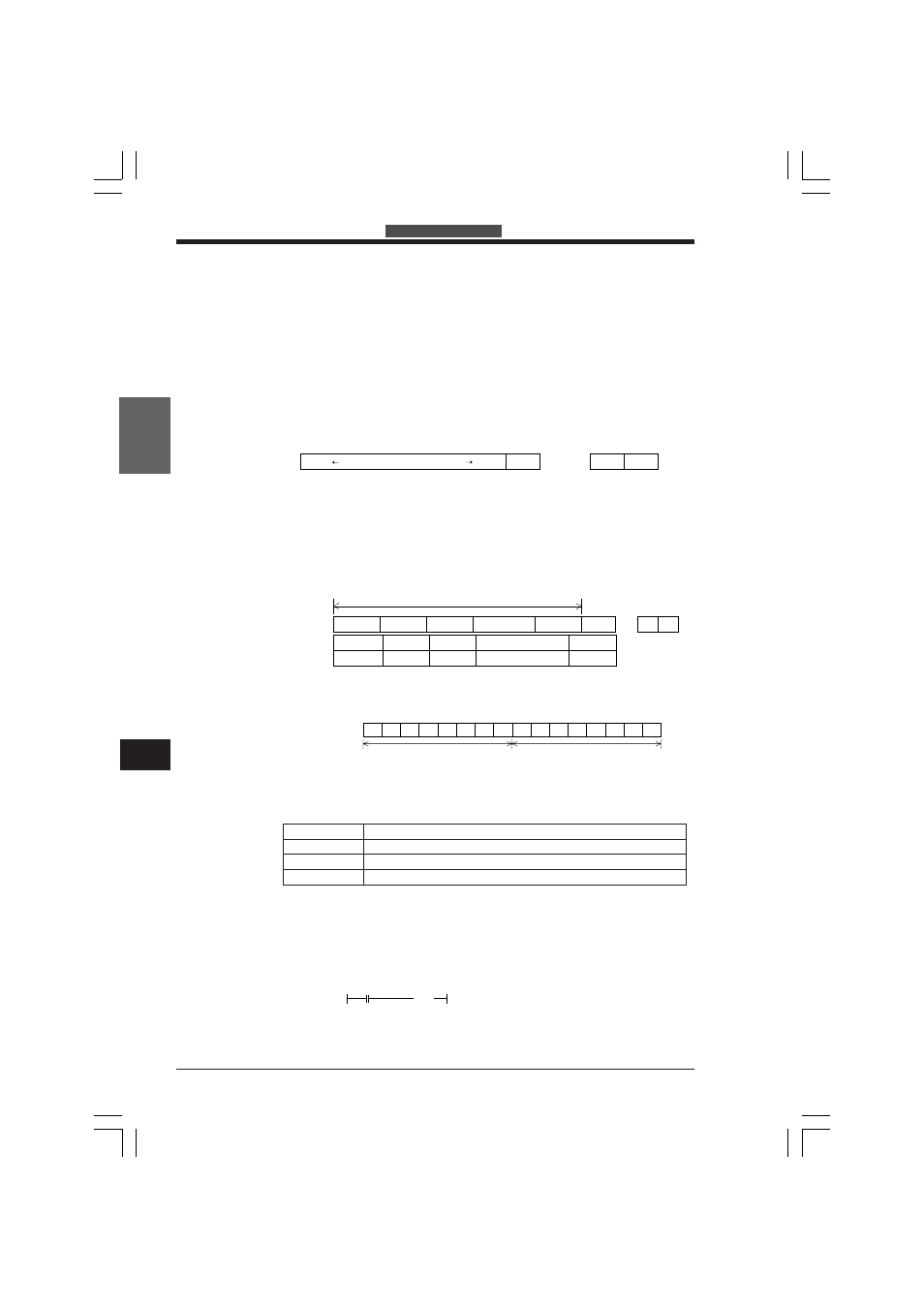
Reception data format
The KV-L2 can receive a maximum of 100 bytes of text data containing the delimiter
CR or CR LF in the last byte.
If transmitted text data includes CR, the KV-L2 transfers the data up to immediately
before CR to the data memory addresses. Text data after CR is loaded as separate
data.
Data memory addresses
The KV-300 can write received text data into the assigned data memory addresses,
one byte per data memory address, in ASCII.
00 is loaded to 8 high-order bits and text data is loaded to 8 low-order bits in ASCII
as follows.
ON/OFF status of special utility relays
The assigned utility relays turn ON only for the first scan when text data is loaded or
an error occurs.
1. First relay no. +0
Turns ON after loading data and transferring it to the data memory addresses. When
it remains ON, data cannot be loaded. Write a program so that this relay turns OFF
after the process is completed. (Data is loaded while the relay is OFF.)
To fetch the ON signal only for one scan, add the following line to the end of the
program.
C
R
Text data (100 bytes max.)
Last byte
or
C
R
L
F
data 1
data 2
data 3
data 99
- - - - - - - - - - -
data 1
data 99
data 2
data 3 to data 98
C
R
C
R
L
F
Received data
Data memory
addresses
Number
Number of data bytes
1st DM no.+00 1st DM no.+01 1st DM no.+02
Number of data bytes
1st DM no.+03 to 1st DM no.+98
1st DM no.+99
or
D15
0
D14
0
D13
0
D12
0
D11
0
D10
0
D09
0
D08
0
D07
0
D06
0
D05
1
D04
1
D03
0
D02
0
D01
0
D00
1
Data memory
High-order 8 bits
Low-order 8 bits
[00]
[ASCII code ]
Relay No.
Description
First relay +0
Turns ON when text data has been loaded.
+1
Turns ON when text data has been loaded but not transferred to DM.
+2
Turns ON when an error occurs during text data reception.
(RES)
∗∗∗∗
∗∗∗∗
First relay no. +0)
(∗∗∗∗
KVHKA Chap 07_5to10.p65
08.3.11, 11:18 AM
298