2 wiring: kv-u5 dc power distribution module, Parts and functions, Kv -300 – KEYENCE Visual KV Series User Manual
Page 193
5.2 Module/Unit Specifications
KV
-300
KV-10/80
1
5
Chapter 5 KV-300 Hardware
1-169
5.2.2
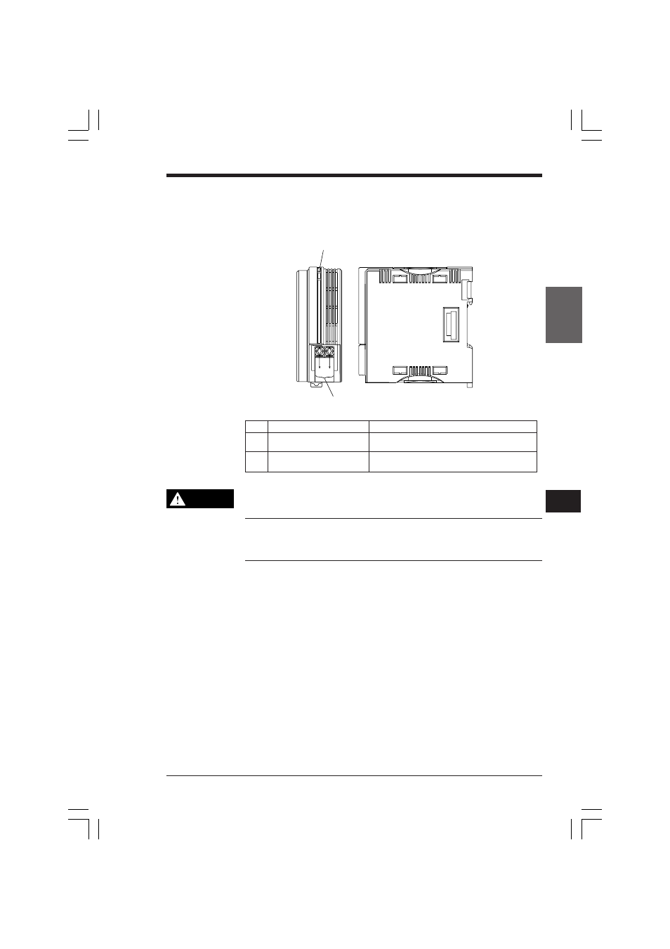
Wiring: KV-U5 DC Power Distribution Module
Parts and functions
1. POWER indicator (green)
2. Power input terminal
(M3 screws) for 24 VDC
No.
Name
Function
1
POWER indicator (green)
Lights when DC power is supplied to the power
input terminals 2.
2
Power input terminals
For 24 VDC power supply
(M3 screws)
Do not connect an AC power supply to the power input terminals; doing so
will damage the KV-U5.
Note 1: Supply power of at least 1.5 times the input capacity to the power input
terminal.
Note 2: Install the KV-U5 in the leftmost position of the system. Install the KV-300
CPU immediately to the right of the KV-U5.
CAUTION
KVHKA Chap 05.p65
08.3.11, 11:14 AM
169
See also other documents in the category KEYENCE Sensors:
- LR-TB2000 Series (12 pages)
- LR-TB5000 Series (12 pages)
- LR-ZB250AN/AP (4 pages)
- LR-ZB250AN/P (3 pages)
- LR-ZBxN/P Series (3 pages)
- LR-ZBxxB (3 pages)
- OP-85135 (1 page)
- PZ-G Series (2 pages)
- PZ-V/M (2 pages)
- PS-N10 Series (12 pages)
- PX-10 (10 pages)
- CZ-V21A(P) (10 pages)
- CZ-K1(P) (8 pages)
- CZ-V1 (8 pages)
- FS-N10 Series (116 pages)
- FS-N10 Series (6 pages)
- FS-N15CN (1 page)
- FU-93(Z) (2 pages)
- FU-V Series (2 pages)
- FS-V30 (6 pages)
- FU-A40 (1 page)
- NU/FS-N Series (16 pages)
- FS-V33(P) (8 pages)
- FS-V21 (4 pages)
- FS-V22 (4 pages)
- FS-V11(P) (4 pages)
- FS-V1(P) (4 pages)
- LV-N10 Series (12 pages)
- LV-N10 Series (112 pages)
- LV-S62 (1 page)
- OP-84350 (1 page)
- LV-SA (10 pages)
- LV-SB (12 pages)
- OP-87305 (1 page)
- LV Series (10 pages)
- LV-B102 (1 page)
- EV-108M(U) (1 page)
- EZ Series (1 page)
- EM Series (1 page)
- ES-M1(P) (3 pages)
- EX-V Series (120 pages)
- EX-500(W) Series (16 pages)
- GV Series (10 pages)
- IA Series (8 pages)
- LB-1000(W) (24 pages)