Connecting to the kv-l2, Kv -300, When using port 1 – KEYENCE Visual KV Series User Manual
Page 317: When using port 2
7.7 Non-procedure Mode Programming
KV-300 Series Only
KV
-300
KV-10/80
Chapter 7 KV-L2 Serial Interface Module
1-293
1
7
Note 1: Communications protocols for devices to be connected must be identical;
otherwise, communication will fail. For the settings of the device to be connected,
refer to the operation manual supplied with the device.
Note 2: The communications protocol settings apply to both ports 1 and 2. The two
ports cannot be set to different protocols
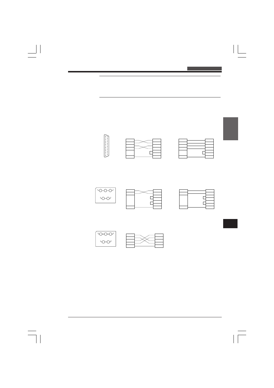
Connecting to the KV-L2
When using port 1
When connecting the KV-L2 to a device with an RS-232C terminal, wire the RS-
232C cables as shown below.
Connect a commercially available RS-232C standard connection cable or null
modem cable to the RS-232C connector at port 1.
When using port 2
1. When using the KV-L2 port 2 set to RS-232C mode, wire the cable as shown
below.
2. When using the KV-L2 port 2 set to RS-422A mode, wire the cable as shown
below.
D-Sub 25-pin
connector
1
23
45
6
789
1
0
11
12
13
14
15
16
17
18
19
20
21
22
23
24
25
2
3
4
5
7
SD
RD
RS
CS
SG
KV-L2
2
3
4
5
6
20
7
SD
RD
RS
CS
DR
ER
SG
2
3
4
5
7
SD
RD
RS
CS
SG
KV-L2
2
3
4
5
6
20
7
SD
RD
RS
CS
DR
ER
SG
External unit
designated as DTE
External unit
designated as DCE
SG
(SG)
SDB RDB
SDA
(SD)
RDA
(RD)
1
3
5
2
4
KV-L2 terminal nos.
3
5
1
SD
RD
SG
KV-L2
3
5
1
SD
RD
SG
KV-L2
2
3
4
5
6
20
7
SD
RD
RS
CS
DR
ER
SG
External unit
designated as DTE
2
3
4
5
6
20
7
SD
RD
RS
CS
DR
ER
SG
External unit
designated as DCE
SG
(SG)
SDB RDB
SDA
(SD)
RDA
(RD)
1
3
5
2
4
KV-L2 terminal nos.
SDA
SDB
RDA
RDB
SG
SDA
SDB
RDA
RDB
SG
KV-L2
External unit
3
2
5
4
1
KVHKA Chap 07_5to10.p65
08.3.11, 11:18 AM
293