KEYENCE LV-SA User Manual
Lv-s series, Instruction manual, Ultra-small digital laser sensor
1
E LV-S-IM
Ultra-small Digital Laser Sensor
LV-S Series
Instruction Manual
Safety Information for LV-S series
Safety precautions on laser products
* The classification is implemented based on IEC60825-1 following the
requirements of Laser Notice No.50 of FDA (CDRH).
Safety Measures for the Laser
■ Laser emission stop input
The laser emission can be stopped by selecting the “Laser emission stop”
signal (20 ms or more) from the input functions and inputting it externally.
The emission stops while the signal is being input. The laser beam is emitted
in 20 ms after the signal input is canceled. The control output functions
according to the received light intensity even while laser emission stop is
input.
Note
When the power is turned on, even when the laser emission stop signal is
input, the laser is emitted for about 60 ms for self-diagnostic purpose.
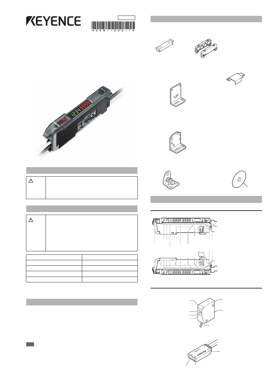
Accessories
■ Amplifier
Mounting bracket: 1
End unit: 2
Instruction Manual: 1
Supplied with LV-11SA (P) Supplied with LV-12SA (P)
■ LV-S31 dedicated accessories
■ LV-S61 dedicated accessories
Mounting bracket: 1
Plate nut: 1
M2 x 12 screw: 2
Reflector (R-6): 1
■ LV-S71/S72 dedicated accessories
Amplifier
■ LV-12SA (P)
■ LV-11SA (P)
Sensor head
■ LV-S31
■ LV-S41
Warning
•
This product is just intended to detect the object(s). Do not use this
product for the purpose to protect a human body or a part of human
body.
•
This product is not intended for use as explosion-proof product. Do
not use this product in hazardous location and/or potentially explosive
atmosphere.
Warning
•
Use of controls or adjustments or performance of procedures other
than those specified herein may result in hazardous radiation expo-
sure.
•
This product employs a semiconductor laser for its light source.
•
Follow the instructions mentioned in this manual. Otherwise, injury to
the human body (eyes and skin) may result.
Precautions on class 1 laser products
•
Do not disassemble this product. Laser emission from this product
is not automatically stopped when it is disassembled.
•
Do not stare into the beam.
Sensor head
LV-S31/S41/S41L/S61/S71/S72
Wavelength
655 nm
Output
290
μW
FDA(CDRH) Part 1040.10*
Class 1 Laser Product
IEC 60825-1
Class 1 Laser Product
Identifying Part Names
■ LV-S41/S41L dedicated accessories
Mounting bracket: 1
Mounting bracket: 1
Plate nut: 1
M3 x 15 screw: 2
Adjustment screwdriver: 1
Mounting bracket: 2
Nut: 4
Beam axis adjustment cap: 1
Facing ring: 2
Washer: 2
φ
30
Output indicator lamp (for control output 2)
SET
button
Digital monitor
Manual button
Channel selection switch
(display settings)
Connector protection cover
Extension connector
MODE button
Dust cover
Output indicator lamp (for control output 1)
Hold lock bar
Receiving section
Transmitting section
Operation indicator (red)
FAR indicator (red)
JUST indicator (green)
NEAR indicator (red)
F
F
N
J
N
Adjustment trimmer
Receiving section
Transmitting section
Operation indicator (red)
96M11665
Document Outline
- Safety Information for LV-S series
- Safety precautions on laser products
- Safety Measures for the Laser
- Accessories
- Identifying Part Names
- Input/Output Circuit Schematic
- Mounting the Amplifier Unit
- Connecting the Sensor Head and the Amplifier Unit
- Mounting and Adjusting the Sensor Head
- Setting Sensitivity
- Fine-adjusting Sensitivity
- Area Detection Mode
- Setting the Display Scaling
- Shift Function
- How to Set up Each Mode (LV-S41/S41L/S61/S71/S72)
- How to Set up Each Mode (LV-S31)
- Toggling the Display
- Interference Protection Function
- Keylock
- Power-save (Eco Mode)
- Default Mode Settings (Initialization)
- Specifications
- Caution on a lustrous workpiece (LVS31)
- Error Indication
- Tips on Correct Use
- WARRANTIES AND DISCLAIMERS