3 system configuration, Kv -300 – KEYENCE Visual KV Series User Manual
Page 365
9.2 Configuration
KV-10/80 Series Only
KV
-300
KV-10/80
Chapter 9 KV-AD4/DA4 Analog I/O Unit
1-341
1
9
➮ For details on how to connect the KV-AD4/DA4 and the KV-10 to 80, see "Connecting to the KV-10
to 80 on page 1-348. For details on how to connect other I/O expansion units, refer to page 1-192.
Pay attention to the following when expanding the system.
Note 1: Only one KV-AD4 and one KV-DA4 can be connected to a single KV-10 to
80. If two or more KV-AD4/DA4s are connected, they will not operate normally.
Note 2: Always connect the KV-AD4/DA4 to the right end of the connection path.
Note 3: When both the KV-AD4 and KV-DA4 are used, make sure that one of
these units is connected to the right end of the connection path and that the other
unit is connected in between. The KV-AD4 and KV-DA4 may be connected in any
order.
9.2.3
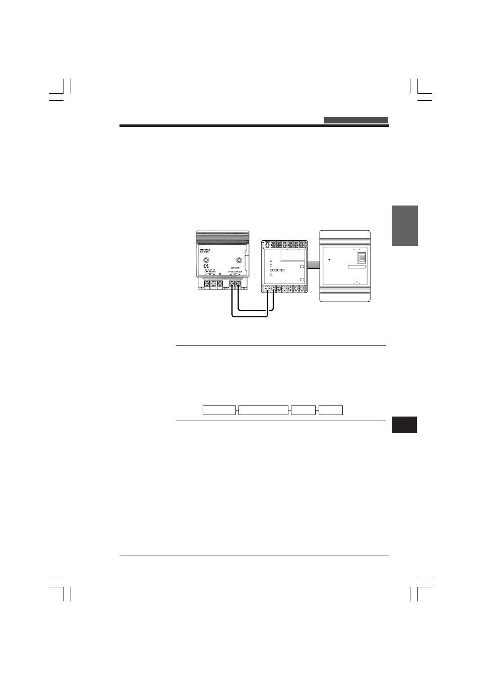
System Configuration
This section describes the system configuration when the KV-AD4/DA4 is connected
to the KV-10 to 80.
The KV-AD4/DA4 can be connected to the KV-10 to 80 as shown in the following
diagram.
One KV-AD4 and KV-DA4 module each can be connected to a single KV-10 to 80.
Other I/O expansion units can be connected to the CPU as specified in the manual.
C0
C1
C2
C3
C4
C5
C6
C7
V0
V1
V2
V3
I0
I1
I2
I3
ANALOG IN
KEYENCE
KV - AD4
POWER
KEYENCE
KV - 10R
Power supply unit
CPU
(KV-10 to 80)
KV-AD4/DA4
KV-10 to 80 I/O expansion unit
KV-AD4 KV-DA4
KVHKA Chap 09.p65
08.3.11, 11:20 AM
341