Visual kv series – KEYENCE Visual KV Series User Manual
Page 175
Chapter 4 KV-D20 Operator Interface Panel
1-151
1
4
Visual KV
Series
4.3 Examples of Ladder Programs
1.
Turn on Bits 0, 5, and 6 of DM1676 ($0061) to enable changing the screen
between the operator, switch comment, and lamp comment screens.
2.
Set the input time constant of input 0004 to 10 µs for pulse input.
3.
The measurement starts when customized switch F1 is pressed.
4.
The measurement stops when customized switch F2 is pressed.
5.
The frequency (Hz) measurement is set when customized switch F3 is pressed.
6.
The rotation (rpm) measurement is set when customized switch F4 is pressed.
7.
Customized lamp 1 illuminates during frequency counter operation.
8.
Customized lamp 2 illuminates during frequency (Hz) measurement.
9.
Customized lamp 3 illuminates during rotation (rpm) measurement.
10. Assign DM1404 to the device displayed on the second line (specify "#31404" in
DM1581), and set the attributes so that the number of spaces at the right end is
"3" ($0030) (DM1681 = $0030).
Assign DM0000 to the device displayed on the third line (specify "#30000" in
DM1582), and set the attributes so that the number of spaces at the right end is
"3" ($0030) (DM1682 = $0030).
11. During frequency (Hz) measurement (relay 1000 is turned off), assign TM30 to
the device displayed on the first line (specify "#24030" in DM1580), and set the
attributes so that only the comment is displayed (Bit 8: ON) (DM1680 = $0100).
Assign DM1405 to the device displayed on the fourth line (specify "#31405" in
DM1583), and set the attributes so that the number of spaces at the right end is
"3" ($0030) and changing the value is disabled (Bit 15: ON) (DM1683 = $8030).
12. During rotation (rpm) measurement (relay 1000 is turned on), assign TM31 to
the device displayed on the first line (specify "#24031" in DM1580), and set the
attributes so that only the comment is displayed (Bit 8: ON) (DM1680 = $0100).
Assign DM0001 to the device displayed on the fourth line (specify "#30001" in
DM1583), and set the attributes so that the number of spaces at the right end is
"3" ($0030) and changing the value is disabled (Bit 15: ON) (DM1683 = $8030).
13. The number of rotations (rpm) is obtained during rotation (rpm) measurement
(when relay 1000 is turned on) using the following equation.
No. of rotations (rpm) = Measured frequency (Hz) x 60 ÷ No. of pulses for 1 rotation
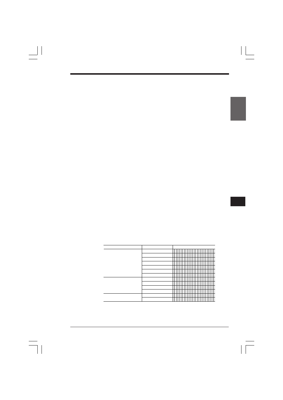
Comment
Relay
Data memory
Temporary memory
2500
2501
2502
2503
2504
2505
2506
DM0000
DM0001
DM1404
DM1405
TM30
TM31
Device
No.
Comment 1
S T A R T
E N D
U N I T
C H A N G E ( H z )
U N I T C H A N G E ( r p m )
M E A S U R I N G
U N I T ( H z )
U N I T ( r p m )
P U L S E
F O R
1
R O T A T I O N : P L S
R O T A T I O N r p m
M E A S U R E M E N T
C Y C L E : m s
F R E Q U E N C Y : H z
* F R E Q U E N C Y C O U N T E R : H z *
* F R E Q U E N C Y C O U N T E R : r p m *
KVHKA Chap 04.p65
08.3.11, 11:13 AM
151