7 i/o connectors, Kv-300 cpu, Kv -300 – KEYENCE Visual KV Series User Manual
Page 207: I/o connectors, Modular connector
5.3 Module/Unit Connections
KV
-300
KV-10/80
1
5
Chapter 5 KV-300 Hardware
1-183
5.3.7
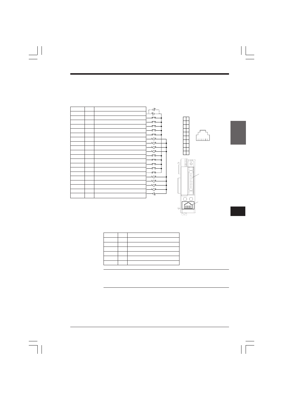
I/O Connectors
KV-300 CPU
I/O connectors
24 VDC
L
L
L
L
L
L
L
L
Load voltage
(See Notes)
Pin No.
I/O
Signal
1
I
Input
COM
2
I
(Interrupt)
0001
3
I
(Interrupt)
0003
4
I
(High speed counter 1)
0005
5
I
(High speed counter 1 phase)
0007
6
I
(High speed counter 1 RES)
0009
7
O
(with resistor)
0500
8
O
(with resistor)
0501
9
O
(with resistor)
0502
10
O
(with resistor)
0503
11
I
(Interrupt)
0000
12
I
(Interrupt)
0002
13
I
(High speed counter 0)
0004
14
I
(High speed counter 0 phase)
0006
15
I
(High speed counter 0 RES)
0008
16
O
0500
17
O
0501
18
O
0502
19
O
0503
20
O
Output
COM
Modular connector
Note 1: Connecting the output load voltage with the incorrect polarity may damage
the output terminals built into the KV CPU.
Note 2: The output connectors of pin nos. 7 to 10 have built-in 1.6 kΩ current
limiting resistors. Use these to connect drivers.
1
2
3
4
5
6
7
8
9
10
11
12
13
14
15
16
17
18
19
20
Modular connector
1 2 3 4 5 6
(Connector terminal Nos.)
I/O connector
A
0
1
2
3
4
5
6
7
8
9
10
11
12
13
14
15
B
0
1
2
3
4
5
6
7
8
9
10
11
12
13
14
15
I/O connector
Modular connector
➮ Refer to page 189 for crimping cables to
connectors.
Pin No.
I/O
Signal
1
—
—
2
—
+5 V power supply output
3
I
RD
4
—
SG
5
O
SD
6
—
—
KVHKA Chap 05.p65
08.3.11, 11:14 AM
183