3 ac power input (kv-24ar/at(p)), Visual kv series – KEYENCE Visual KV Series User Manual
Page 52
Chapter 1 Configuration and Specifications
1-28
1
Visual KV
Series
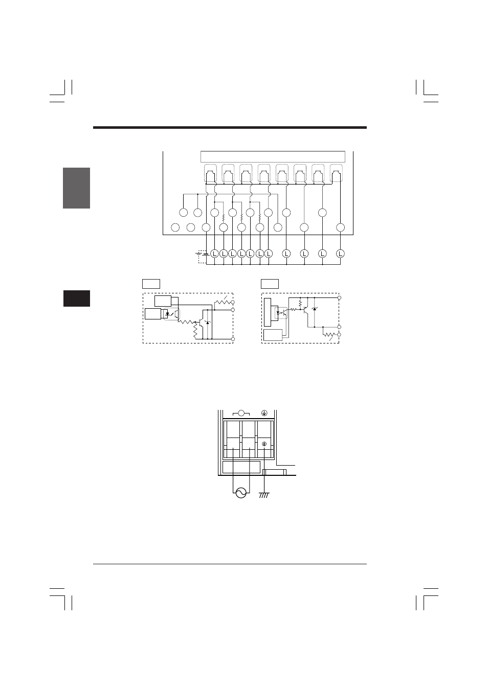
1.6 KV-24AR/AT(P)/DR/DT(P) (24-I/O Basic Unit)
■ Output circuit diagram
1.6.3
AC Power Input (KV-24AR/AT(P))
V2
R5O1
501
R502
502
V3
503
505
504
507
506
R500
500
V1
C3
0V
24V
*
500
to 507
C3
R500
to R502
1.6 kΩ
W
1
2
Internal circuit
Insulating
power
supply
Internal
circuit
L
AC100V-240V
0.6A 50/60Hz
FG
N
L
~
N
• A 1.6 kΩ current limiting resistor is built in each of
R500 to R502 (to connect a motor driver).
• V1 to V3 are short-circuited inside (so they can
be used as a relay terminal block).
* For KV-24ATP/DTP
Insultating
power
supply
Internal circuit
R500 to R502
C3
500 to 507
1.6 kΩ
W
1
2
• A 1.6 kΩ current limiting resistor is built in each of
R500 to R502 (to connect a motor driver).
• V1 to V3 are short-circuited inside (so they can
be used as a relay terminal block).
PNP
NPN
KVHKA Chap 01.p65
08.3.11, 11:10 AM
28
- LR-TB2000 Series (12 pages)
- LR-TB5000 Series (12 pages)
- LR-ZB250AN/AP (4 pages)
- LR-ZB250AN/P (3 pages)
- LR-ZBxN/P Series (3 pages)
- LR-ZBxxB (3 pages)
- OP-85135 (1 page)
- PZ-G Series (2 pages)
- PZ-V/M (2 pages)
- PS-N10 Series (12 pages)
- PX-10 (10 pages)
- CZ-V21A(P) (10 pages)
- CZ-K1(P) (8 pages)
- CZ-V1 (8 pages)
- FS-N10 Series (6 pages)
- FS-N10 Series (116 pages)
- FS-N15CN (1 page)
- FU-93(Z) (2 pages)
- FU-V Series (2 pages)
- FS-V30 (6 pages)
- FU-A40 (1 page)
- NU/FS-N Series (16 pages)
- FS-V33(P) (8 pages)
- FS-V21 (4 pages)
- FS-V22 (4 pages)
- FS-V11(P) (4 pages)
- FS-V1(P) (4 pages)
- LV-N10 Series (12 pages)
- LV-N10 Series (112 pages)
- LV-S62 (1 page)
- OP-84350 (1 page)
- LV-SA (10 pages)
- LV-SB (12 pages)
- OP-87305 (1 page)
- LV Series (10 pages)
- LV-B102 (1 page)
- EV-108M(U) (1 page)
- EZ Series (1 page)
- EM Series (1 page)
- ES-M1(P) (3 pages)
- EX-V Series (120 pages)
- EX-500(W) Series (16 pages)
- GV Series (10 pages)
- IA Series (8 pages)
- LB-1000(W) (24 pages)