KEYENCE EV-130M(U) User Manual
Ev series, Instruction manual, Warranties and disclaimers
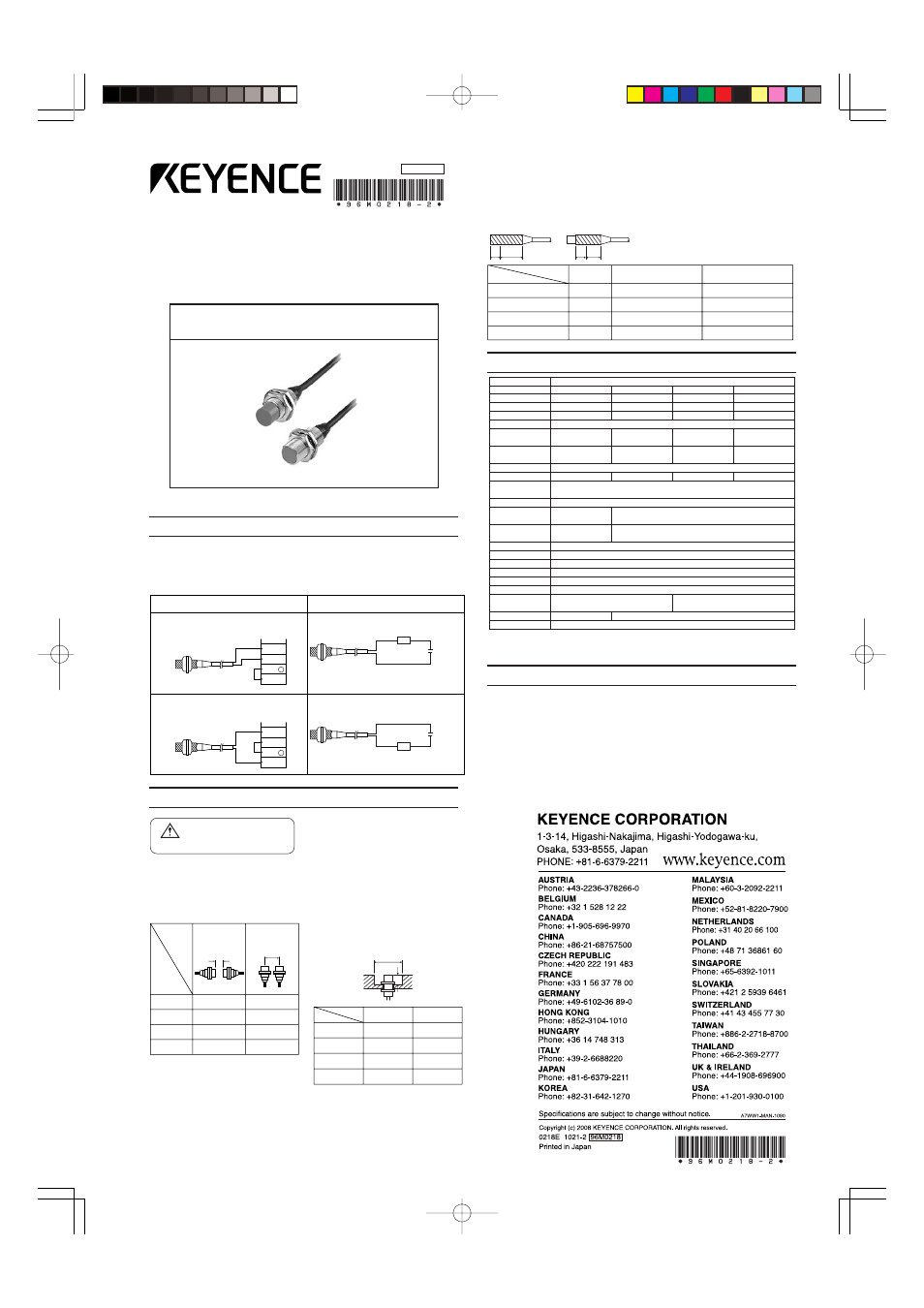
DC two-wire self contained
amplifier proximity sensors
EV series
Instruction Manual
96M0218
KEYENCE, at its sole option, will refund, repair or replace at no charge any defective
Products within 1 year from the date of shipment. Unless stated otherwise herein, the
Products should not be used internally in humans, for human transportation, as safety
devices or fail-safe systems. EXCEPT FOR THE FOREGOING, ALL EXPRESS, IMPLIED
AND STATUTORY WARRANTIES, INCLUDING WARRANTIES OF MERCHANTABILITY,
FITNESS FOR A PARTICULAR PURPOSE AND NONINFRINGEMENT OF
PROPRIETARY RIGHTS, ARE EXPRESSLY DISCLAIMED. KEYENCE SHALL NOT BE
LIABLE FOR ANY DIRECT, INDIRECT, INCIDENTAL, CONSEQUENTIAL OR OTHER
DAMAGES, EVEN IF DAMAGES RESULT FROM THE USE OF THE PRODUCTS IN
ACCORDANCE WITH ANY SUGGESTIONS OR INFORMATION PROVIDED BY
KEYENCE. In some jurisdictions, some of the foregoing warranty disclaimers or damage
limitations may not apply.
E 1110-2
WARRANTIES AND DISCLAIMERS
EV-130M / U
M30
10mm
±
10%
27mm
±
10%
250Hz
EV-118M / U
M18
5mm
±
10%
15mm
±
10%
350Hz
EV-112M / U
M12
2.5mm
±
10%
8mm
±
10%
600Hz
EV-108M / U
M8
1.5mm
±
10%
4mm
±
10%
800Hz
Stainless steel
Type
Model
Size
Detecting distance / M
Detecting distance / U
Detectable object
Hysteresis
Response frequency
Operation mode
Power supply
Ratings
Degree of protection
Operating temperature
Relative humidity
Vibration
Housing material
Cable length
Standard target / M
(iron,t =1mm)
Standard target / U
(iron,t =1mm)
Temperature fluctuation
Control output
(switching capacity)
Protective circuit
Shock
10
×
10 mm
12
×
12 mm
18
×
18 mm
30
×
30 mm
20
×
20 mm
30
×
30 mm
50
×
50 mm
70
×
70 mm
5 to 80mA
Reversed polarity,
surge voltage
M:Shielded/U:Non-shielded
Ferrous metals (see Characteristics for non-ferrous metals)
10% max. of detecting distance / 20% max. of detecting distance within –10 to + 70
°
C (–14 to 158
°
F), No freezing
M:
±
10%max. of detecting distance at 23
°
C (73.4
°
F)
within –25 to + 70
°
C (–13 to 158
°
F), No freezing
N.O. (N.C. output type available for all models)
5 to 200mA
Reversed polarity, overcurrent, surge voltage
12 to 24 VDC Ripple (p-p) : 20% max.
Current consumption (leakage current) : 1.0mA max. Residual voltage : 3.6V max. (with 2-m cable)
IP-67
–25 to + 80
°
C (–13 to 176
°
F), No freezing
35 to 95%, No condensation
10 to 55Hz 1.5mm double amplitude in X, Y, and Z directions, 2 hours respectively
1000 m/s
2
in X, Y, and Z
directions, 3 times respectively
500 m/s
2
in X, Y, and Z
directions, 3 times respectively
Nickel-plated brass
2m
*1
Brown
Blue
IN
0V
+
24V
COM
+
Brown
Blue
DC12to24V
load
Connection to a programmable controller
Connection to relay load
Built-in DC power supply (external supply)
(NPN INPUT)
Brown
Blue
IN
0V
+
24V
COM
--
Brown
Blue
DC12to24V
load
Built-in DC power supply (external supply)
(PNP INPUT)
(PNP INPUT)
(NPN INPUT)
Connections Diagram
All the models of the EV series proximity sensors (except for M8) are provided with a built
in short-circuit protection circuit. The sensor will not therefore be damaged even if it is directly
connected to a power source. With no load connected, however, the sensor will not detect
anything even when it is connected to a power source. Connect the brown cord of the
proximity switch sensor to the ( + ) posivtive side, and the blue cord the ( – ) negative side
for NPN input.
Hints on Correct Use
■
Wiring
• Route the sensor cable separately from
the motor power cable or high tension
cables as the sensor may malfunction as a
result of noise.
• The sensor cable length should be 200m
(656ft.) or less using a cable with a conduc-
tor cross-section area equal to or greater
than that of the standard cable.
■
Effect by ambient metal
Sensors of shielded type can be flush-
mounted into metal. As for sensors of
unshielded type, however, the distance longer
than the value shown in the table below shall
be given between a sensor of unshielded
type and metal.
Distance
Model
EV-108U
EV-112U
EV-118U
EV-130U
25
55
70
120
13
20
25
28
A
B
(mm)
(mm)
øA
B
Do not use this product for
the purpose of protecting the
human body.
Warning
■
Mutual interference
When mounting two or more sensors of the
same model in opposition or in juxtaposition
t o e a c h o t h e r , b e s u r e t o p r o v i d e
spacingbetween the two sensors for each
model as shown in the table below.
Opposed position
Distance
Model
EV-108M/U
EV-112M/U
EV-118M/U
EV-130M/U
20/30
30/55
40/70
100/160
11/28
22/62
28/88
50/180
Juxtaposition
mm
mm
Specifications
■
Tightening torque
When mounting the sensor, be sure to use the
toothed washer suppIied as an accessory.
Tighten the washer to less than the torque
specified for each model in the table below.
Shielded
Unshielded
Distance
Model
EV-108M·EV-108U
3
EV-112M·EV-112U
6
EV-118M·EV-118U
7
EV-130M·EV-130U
10
8Nm max.
15Nm max.
60Nm max.
120Nm max.
9Nm max.
30Nm max.
70Nm max.
180Nm max.
Dimension
A
(mm)
A part
B part
■
Leakage current
With the EV series sensors, a leakage cur-
rent flows through the sensor even when the
output is turned off. For this reason, some
voltage may remain in the load connected to
the sensor, which may result in unwanted
operation or chattering, depending on the
load (Ex. Programmable logic controller). In
such a case, be sure to connect a resistor in
parallel with the load to minimize the residual
voltages at both ends of the load.
■
Relay Load
Note that the sensor's residual voltage is
3.4V. (A 12 VDC relay cannot be operated.)
■
Low load current
If the load current is less than 5mA, connect
a bleader resistor in parallel with the load so
that a current of more than 5mA flow through
the sensor.
*1 EV-108U/112U/118U:
±
10% of detecting distance at 23
°
C (73.4
°
F) within -10 to +70
°
C (14 to
158
°
F)
EV-130U: -5 to +20% of detecting distance at 23
°
C (73.4
°
F) within -10 to +70
°
C (14 to 158
°
F)