8 writing analog output, Kv -300 – KEYENCE Visual KV Series User Manual
Page 351
8.4 Programming
KV-300 Series Only
KV
-300
KV-10/80
Chapter 8 KV-AN6 Analog I/O Module
1-327
1
8
8.4.8
Writing Analog Output
The following example describes how to write analog output.
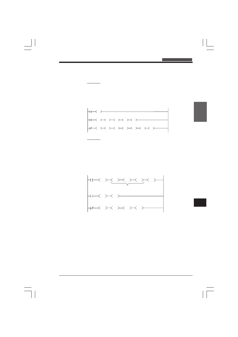
Example 1
Output the data written into DM0000 to analog output ch. 1 of the KV-AN6 module
No. 1 (±10 V output range)
•
When input 0000 is ON, +10 V is output.
•
When input 0000 is OFF, -10 V is output.
Ladder diagram
Example 2
Input trimmer variable data by using analog timer ch. 0 of the KV-300 CPU and
output voltage to analog output ch. 1 of the KV-AN6 module no. 1.
•
When input 0000 is ON ( 0 to 10 V), voltage increases when trimmer of analog
timer is turned clockwise.
•
When input 0000 is OFF (0 to -10 V), voltage decreases when trimmer is turned
clockwise.
•
Output range of ±10 V is used.
Ladder diagram
Trimmer input
Variable from 0 to
32000
Trimmer variable (0
to 32000)
0 to 10 V
When input 0000 is
ON, outputs 0 to 10 V
to analog output ch.
1.
When input 0000 is
OFF, outputs 0 to -
10 V to analog
output ch. 1.
2002
0
TMIN
#00100
MUL
DM0000
STA
#00320
MUL
#00249
DIV
0000
DM0000
LDA
DM9004
STA
0000
DM0000
LDA
COM
#00001
ADD
DM9004
STA
Inputs 10 V to
DM0000.
2002
0000
DM0000
LDA
#01000
MUL
#00005
DIV
#00016
MUL
DM9004
STA
0000
DM0000
LDA
#01000
MUL
#00005
DIV
#00016
MUL
COM
DM9004
STA
#00001
ADD
#00010
DW
DM0000
When input 0000 is
ON, outputs +10 V
from ch. 1.
When input 0000 is
OFF, outputs -10 V
from ch. 1.
KVHKA Chap 08.p65
08.3.11, 11:19 AM
327