Wiring diagrams, Kv -300, Kv-ad4 analog input terminal – KEYENCE Visual KV Series User Manual
Page 370: Chapter 9 kv-ad4/da4 analog i/o unit, Voltage input wiring current input wiring
9.3 Installation
KV-10/80 Series Only
KV
-300
KV-10/80
Chapter 9 KV-AD4/DA4 Analog I/O Unit
1-346
9
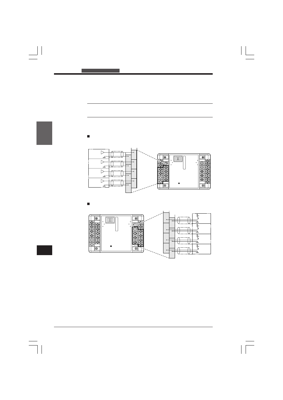
Wiring diagrams
KV-AD4 Analog Input Terminal
Refer to the following wiring diagrams when wiring the analog input terminals.
Note: Make sure that the terminals (channels) to be wired have been set by the
input mode selection switches.
→ For details, see "Setting the KV-AD4 Input Mode" on page 1-344.
C3
C2
C1
C0
V3
V2
V1
V0
C0
C1
C2
C3
C4
C5
C6
C7
V0
V1
V2
V3
I0
I1
I2
I3
ANALOG IN
KEYENCE
KV - AD4
POWER
Voltage output
instrument
Voltage signal
ch3
Voltage signal
ch2
Voltage signal
ch1
Voltage signal
ch0
Shielded cable
Shielded cable
Shielded cable
Shielded cable
Analog signal wire
Terminal
(Input source side)
C0
C1
C2
C3
C4
C5
C6
C7
V0
V1
V2
V3
I0
I1
I2
I3
ANALOG IN
KEYENCE
KV - AD4
POWER
I3
I2
I1
I0
C7
C6
C5
C4
Shielded cable
Shielded cable
Shielded cable
Shielded cable
Analog signal
wire
Terminal
(Input source side)
Current output
instrument
Current
signal
ch3
Current
signal
ch2
Current
signal
ch1
Current
signal
ch0
Voltage input wiring
Current input wiring
KVHKA Chap 09.p65
08.3.11, 11:20 AM
346