2 configuration, 1 part names and functions, Kv-ad4 – KEYENCE Visual KV Series User Manual
Page 359: Kv -300
9.2 Configuration
KV-10/80 Series Only
KV
-300
KV-10/80
Chapter 9 KV-AD4/DA4 Analog I/O Unit
1-335
1
9
9.2
Configuration
9.2.1
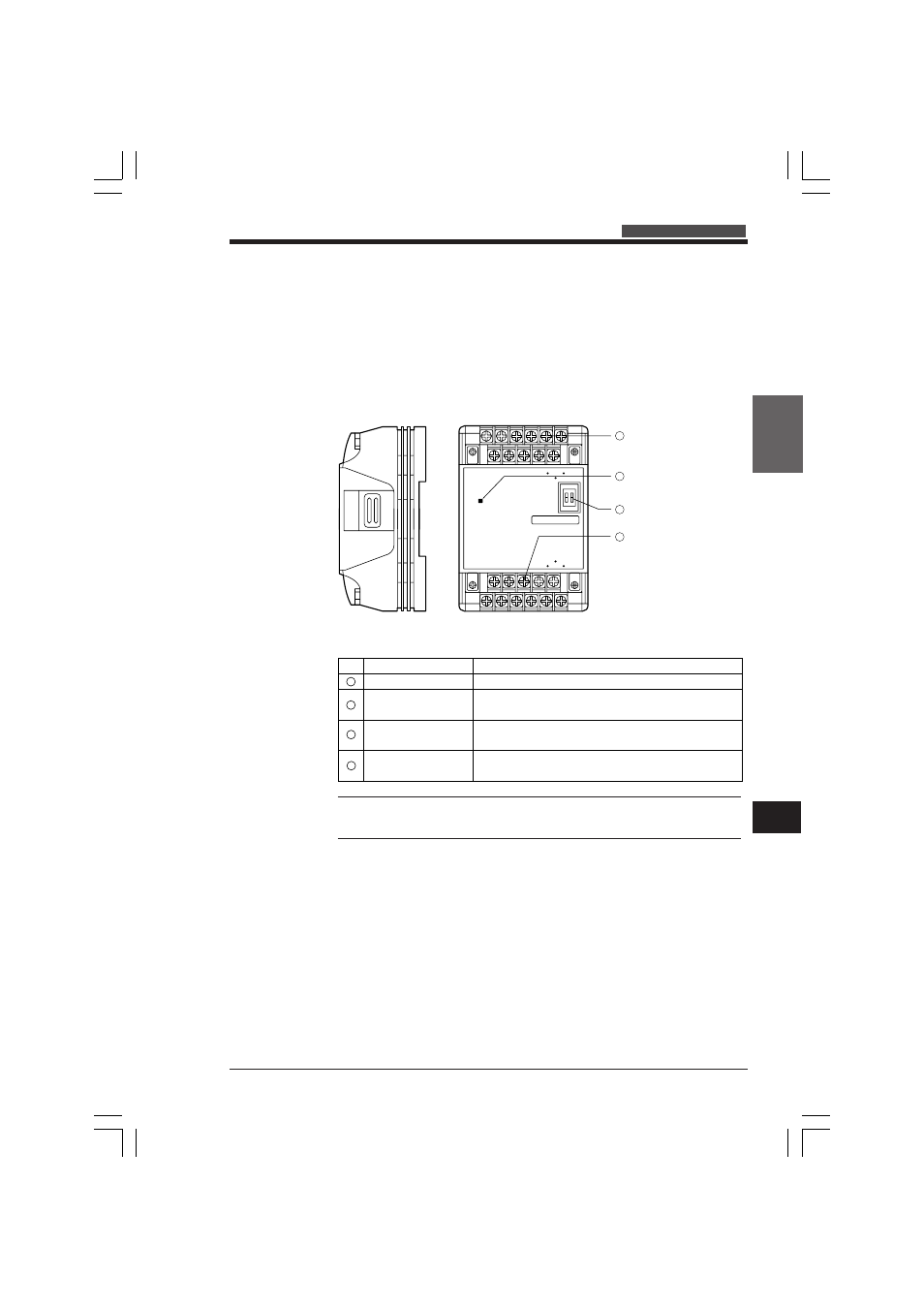
Part Names and Functions
This section describes the names and functions of parts on the KV-AD4/DA4.
KV-AD4
The following describes the names and functions of parts on the KV-AD4.
Note: A terminal for connecting external instruments is called a "channel." This is
sometimes abbreviated to "ch." Only one external instrument terminal is connected
to a single channel.
C0
C1
C2
C3
C4
C5
C6
C7
V0
V1
V2
V3
I0
I1
I2
I3
ANALOG IN
POWER
KEYENCE
KV - AD4
* Protective cover is attached
at purchase.
* Protective cover is attached
at purchase.
Voltage input terminal block
2
POWER indicator
1
Input mode selector switch
4
Current input terminal block
3
Lights red when power is being supplied.
Terminal for connecting to external instruments
that are used as the voltage input source.
No.
Terminal for connecting to external instruments
that are used as the current input source.
DIP switch for selecting the input mode
(voltage or current)
POWER indicator
Voltage input
terminal block
Input mode selector
switch
Name
Function
Current input
terminal block
1
2
3
4
KVHKA Chap 09.p65
08.3.11, 11:20 AM
335