Connecting to the kv-10/16/24/40/80, Connecting kv-l2s, Kv -300 – KEYENCE Visual KV Series User Manual
Page 274: When using port 2 (set to rs-422a mode), When using port 1, When using port 2 (set to rs-232c mode), When using port 1 (1:1 connection), 3 installation kv-300 series only, Chapter 7 kv-l2 serial interface module, The following figure shows the wiring connections
7.3 Installation
KV-300 Series Only
KV
-300
KV-10/80
Chapter 7 KV-L2 Serial Interface Module
1-250
7
When using port 2 (set to RS-422A mode)
The following figure shows the wiring connections.
When connecting multiple KV-L2s through port 2 (set to RS-422A mode)
The following figure shows the wiring connections. The PC serves as the master
unit.
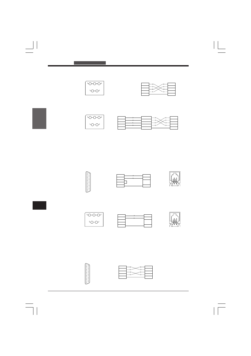
Connecting to the KV-10/16/24/40/80
Connect the KV-L2 to the KV-10/16/24/40/80 through the RS-232C port.
Set the KV-L2 to non-procedure mode.
When using port 1
Use the optional connection cable (OP-96368) and a D-Sub 25-pin connector (OP-
96369) to connect the KV-L2 to the RS-232C connector.
When using port 2 (set to RS-232C mode)
The following figure shows the wiring connections.
Connecting KV-L2s
KV-L2s can be connected either through RS-232C or RS-422A connections. Set the
KV-L2s to either KV or non-procedure modes.
When using port 1 (1:1 connection)
Use an RS-232C cable. The following figure shows the wiring connections.
SG
(SG)
SDB RDB
SDA
(SD)
RDA
(RD)
1
3
5
2
4
KV-L2 terminal nos.
3
5
4
SD
RD
SG
SD
RD
KV-L2
KV CPU
SG
3
5
1
5
4
3
2
KV CPU pin nos.
D-Sub 25-pin
connector
1
23
4
5
6
7
8
9
10
11
12
13
14
15
16
17
18
19
20
21
22
23
24
25
2
3
4
5
7
2
3
4
5
7
SD
RD
RS
CS
SG
SD
RD
RS
CS
SG
KV-L2
KV-L2
SG
(SG)
SDB RDB
SDA
(SD)
RDA
(RD)
1
3
5
2
4
KV-L2 terminal nos.
SDA
SDB
RDA
RDB
SG
SDA
SDB
RDA
RDB
SG
KV-L2
PC
3
2
5
4
1
SG
(SG)
SDB RDB
SDA
(SD)
RDA
(RD)
1
3
5
2
4
KV-L2 terminal nos.
3
2
5
4
1
SDA(3)
SDB(2)
RDA(5)
RDB(4)
SG(1)
SDA
SDB
RDA
RDB
SG
KV-L2
KV-L2
SDA
SDB
RDA
RDB
SG
PC
2
3
4
5
7
3
5
4
SD
RD
RS
CS
SG
SD
RD
SG
KV-L2
KV CPU
5
4
3
2
D-Sub 25-pin connector
(OP-96369)
Connection cable
(OP-96368)
KV CPU pin nos.
D-Sub 25-pin
connector
1
23
4
5
6
7
8
9
10
11
12
13
14
15
16
17
18
19
20
21
22
23
24
25
KVHKA Chap 07_1to4.p65
08.3.11, 11:18 AM
250