Rockwell Automation 2098-UWCPRG Ultraware Software User Manual User Manual
Page 99
Rockwell Automation Publication 2098-UM001G-EN-P - February 2011
101
Configuring the Ultra3000 Drive Chapter 3
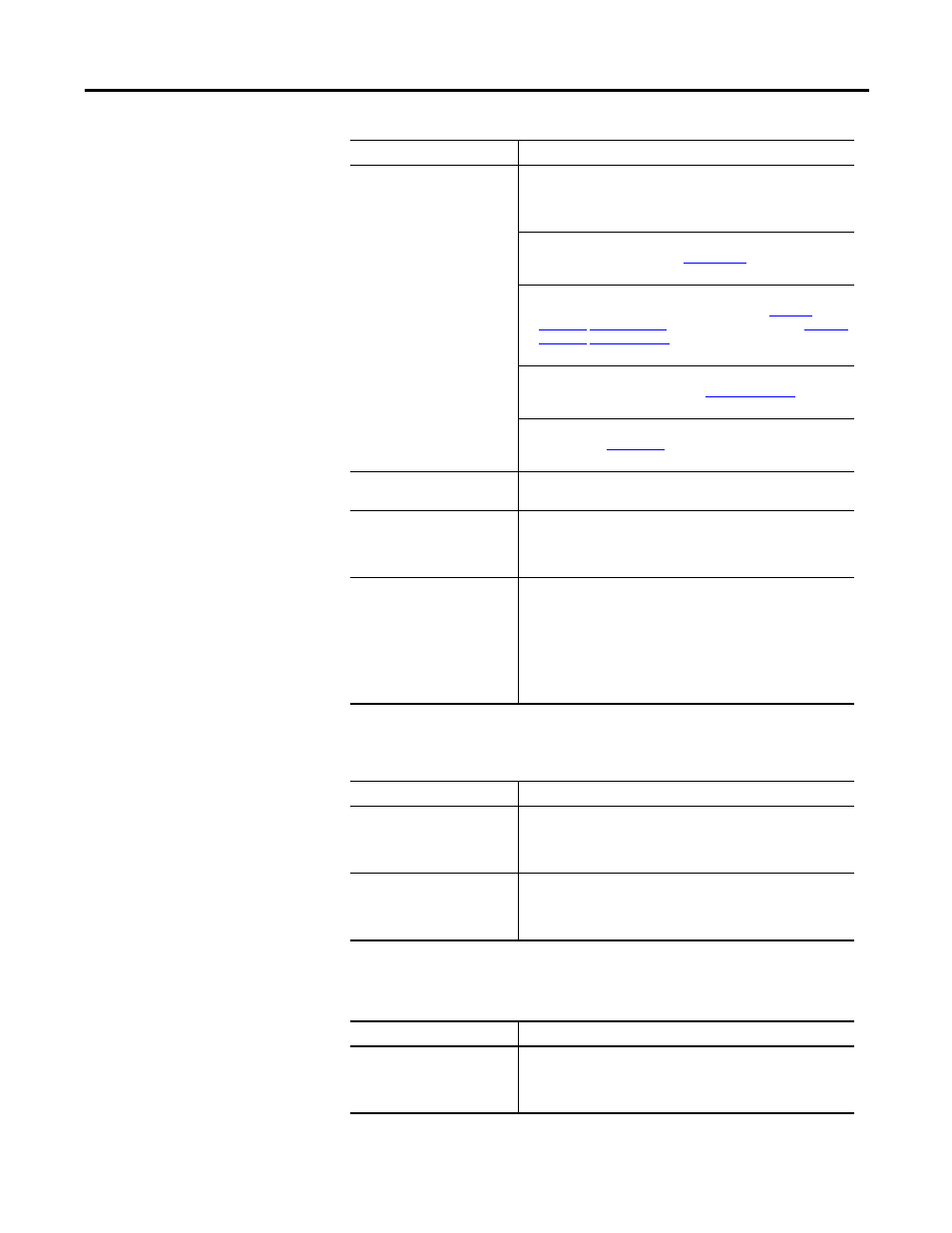
The following status is displayed by default for an Ultra3000 Drive in the Digital
Outputs window:
The following command can be executed for a Digital Outputs window of an
online drive:
Output 1 – 4 (cont.)
• Tracking: An inactive state indicates that the absolute
encoder position has been output and the encoder outputs
are now tracking the motor encoder inputs. This input is used
in conjunction with the Position Strobe input function.
• Up to Speed: An active output state indicates motor velocity
feedback is greater than the
Up to Speed
setting in the
Ultra3000 Drive window.
• Within Position Window: An active output state indicates
that the position error has been less than the
Position
Functions
In Position Size
setting for longer than the
Position
Functions
In Position Time
setting in the Ultra3000 Drive
window.
• Within Speed Window: An active output state indicates that
the velocity error is less than the
In Speed Window
setting in
the Ultra3000 drive window.
• Zero Speed: An active output state indicates that the speed is
less than the
Zero Speed
setting in the Ultra3000 drive
window.
Relay
The function to be assigned to the relay. The selections are the
same as for the Digital Outputs.
Brake Active Delay
The time delay between enabling the drive and activating the
Brake output, that releases the motor brake. Negative values
indicate the time that the function is activated before enabling
the drive. The value has a range of -32,767…32,767 ms.
Brake Inactive Delay
The time delay between disabling the drive and deactivating the
Brake output, that applies the motor brake. Negative values
indicate the time that the Brake output is deactivated before
disabling the drive. The value has a range of
-32,767…32,767 ms.
Note: If a drive fault occurs when a negative value is assigned
to the Brake Inactive Delay parameter, the drive is disabled and
the Brake output is activated simultaneously.
Status
Description
Output 1 – 4 State
The current state, or condition, of each digital output is depicted
by a light bulb icon, as follows:
• ON: a bright light bulb
• OFF: a darkened light bulb.
Relay State
The current state, or condition, of the Relay is depicted by a light
bulb icon, as follows:
• ON: a bright light bulb
• OFF: a darkened light bulb.
Command
Description
Override Outputs
Opens the Override Outputs window where you can:
• place individual outputs in override mode or normal mode
• turn outputs in override mode on or off
• monitor the state of the outputs
Parameter
Description