Understanding the digital outputs window – Rockwell Automation 2098-UWCPRG Ultraware Software User Manual User Manual
Page 180
182
Rockwell Automation Publication 2098-UM001G-EN-P - February 2011
Chapter 4 Configuring the Ultra5000 Drive
Understanding the Digital
Outputs Window
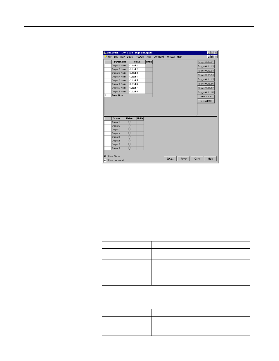
The Properties window for the Digital Outputs branch looks like this
Use the Digital Outputs window to name, monitor, and toggle the status of the
eight digital outputs.
You can edit parameters for both an online and an offline Digital Outputs
branch. However, you can monitor status, and execute direct commands
(executed through the Ultraware interface, rather than through a compiled,
loaded and executed program) only for a Digital Outputs branch that is the child
of an online drive.
The following parameters can be entered and edited in the Digital Outputs
window.
The following display is the default status for a Digital Outputs branch of an
online drive.
Parameter
Description
Output 1 – 8 Name
Type in the name of the output. The default value is a number
from 1 to 8.
Output 1 – 8 Polarities
The desired polarity for each output.
Active High: The output is turned ON by applying a positive
voltage to the output.
Active Low: The output is turned ON by setting the voltage at
the output to zero.
Status
Description
Output 1 – 8 State
The current state, or condition, of each digital output is depicted
by a light bulb icon, as follows:
• ON: A bright light bulb
• OFF: A darkened light bulb.