Understanding the analog outputs window – Rockwell Automation 2098-UWCPRG Ultraware Software User Manual User Manual
Page 101
Rockwell Automation Publication 2098-UM001G-EN-P - February 2011
103
Configuring the Ultra3000 Drive Chapter 3
Understanding the Analog
Outputs Window
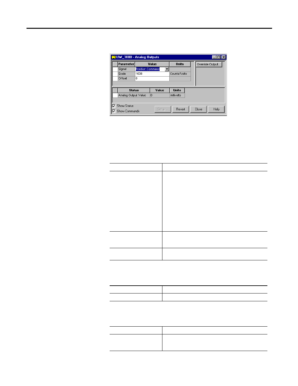
The Properties window for Analog Outputs looks like this.
Use the Analog Outputs window to assign drive signals to analog outputs,
monitor the status of Analog Output, and open a window where you can monitor
and override the analog output value.
The Analog Outputs parameters window has these parameters:
The following status is displayed by default for an Ultra3000 drive in the Analog
Outputs window:
The following command can be executed for a Analog Outputs window of an
online drive:
Parameter
Description
Signal
The drive signal to be assigned to the analog output:
• Unassigned: No signals assigned to the output.
• Current Average: The average value of Current Command.
• Current Command: The commanded current to the motor.
• Current Feedback: The actual current sent to the motor
• Position Command: The commanded motor position.
• Position Error: The difference between commanded and
actual motor position.
• Position Feedback: The output of the position control loop.
• Velocity Command: The commanded motor velocity.
• Velocity Error: The difference between commanded and
actual motor velocity.
• Velocity Feedback: The output of the velocity control loop.
Scale
The output scale in units per volt. It is dependent on the signal
selected. The value is reset to 0 whenever the signal selection is
changed.
Offset
The offset for the analog output. It has a range of
-10,000…10,000 mV.
Status
Description
Analog Output Value
The Analog value, in millivolts, presently being output.
Command
Description
Override Output
Opens the Analog Output Control window, where you can:
• edit the value of the analog output
• monitor the voltage level of the analog output.