Understanding the oscilloscope window – Rockwell Automation 2098-UWCPRG Ultraware Software User Manual User Manual
Page 186
188
Rockwell Automation Publication 2098-UM001G-EN-P - February 2011
Chapter 4 Configuring the Ultra5000 Drive
Understanding the
Oscilloscope Window
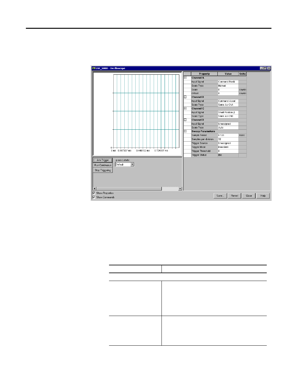
The Properties window for the Oscilloscope looks like this
Use the Oscilloscope window to trace one of four drive signals by:
•
Configuring the oscilloscope by selecting a the drive signal to trace.
•
Executing commands that run the oscilloscope's tracing function
continuously or in response to the configured trigger.
•
Monitoring the oscilloscope as it traces the selected drive signal.
The Oscilloscope window has these parameters and commands associated with it.
Parameter Description
Channel A, B, C and D
Input Signal
Assign a drive signal to the selected Channel (A, B, C or D) from
the Channel Setup dialog box that opens when you click the
down arrow to the right of this input box.
Note: The resolution of this signal may be confusing if Velocity
Feedback is selected. See the topic Velocity Motor Feedback
Resolution for information on how resolution is derived for
various motor and feedback combinations.
Scale Type
Scale Types are:
• Auto
• Manual
• Same As ChA (available for Channels B,C and D)
• Same As ChB (available for Channels C and D)
• Same as ChC (available for Channel D only)