Rockwell Automation 2098-UWCPRG Ultraware Software User Manual User Manual
Page 175
Rockwell Automation Publication 2098-UM001G-EN-P - February 2011
177
Configuring the Ultra5000 Drive Chapter 4
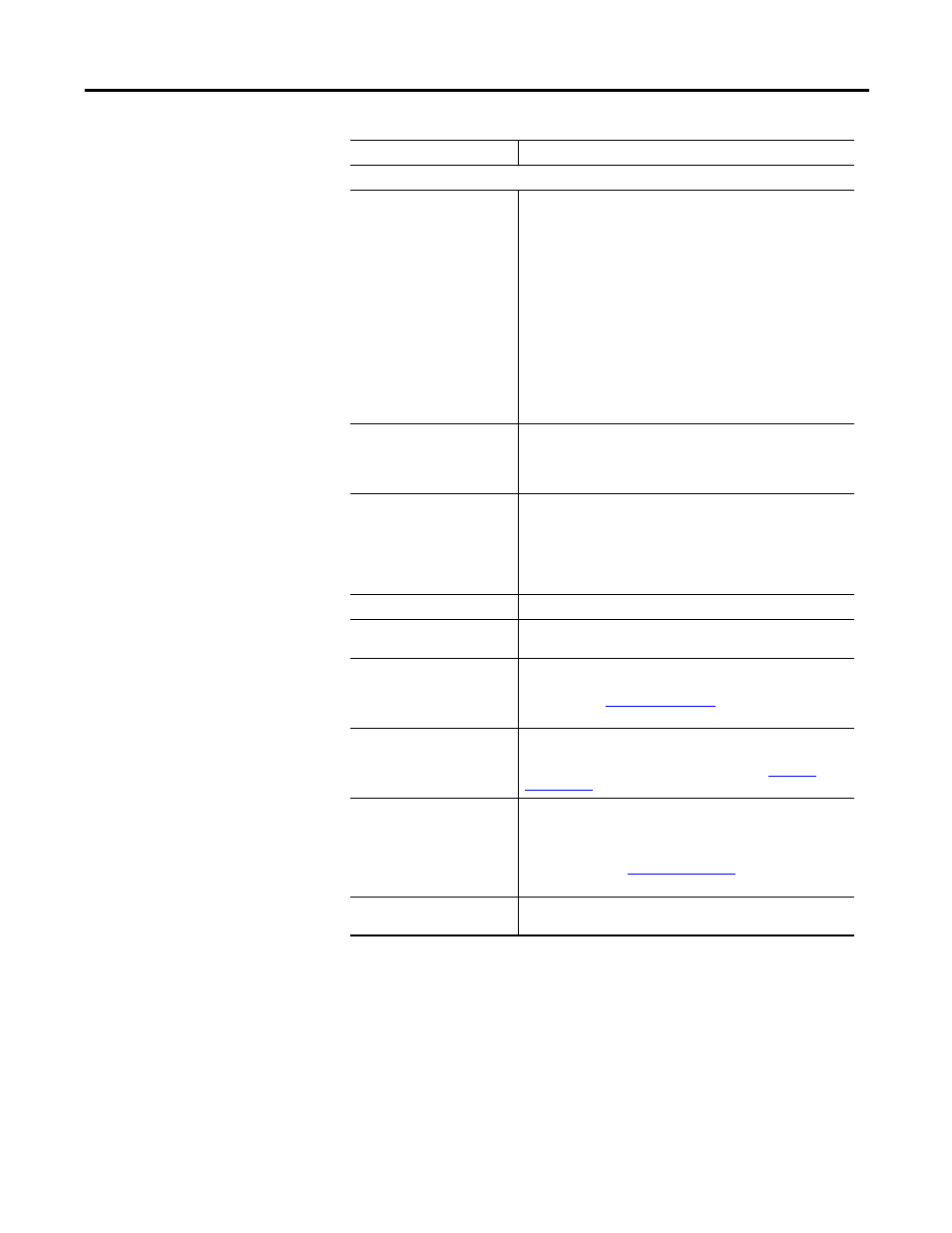
Output Encoder
Mode
Specify how to configure the auxiliary encoder connection of the
drive:
Disabled: The auxiliary encoder connection is used as an input.
The Aux Encoder firmware object contains the position as read
from the input.
Hardware: The auxiliary encoder connection are used for output.
The Encoder Output object is configured to directly pass the
motor encoder position to the output as well as the Aux Encoder
firmware object.
Software: The auxiliary encoder connection is used for output.
The Encoder Output object is configured to pass the software
filtered motor encoder position to the
output as well as the Aux Encoder firmware object. The Divider
and Limit properties, listed below, are used to perform the
filtering in this mode.
Limit
Maximum Output Frequency: The encoder output frequency
limit.
Note: This parameter is active only if Software is selected as
the Output Mode.
Divider
Type the amount of division used for generating output encoder
signals. For example, if the Divider is set to 4, the encoder
output frequency is 1/4th the encoder
input frequency.
Note: This parameter is active only if Software is selected as
the Output Mode.
Ratchet Settings
If Yes is set:
Ignore Negative Input
Negative direction master encoder input generates NO motor
movement.
Negate Negative Input
Master encoder input in a negative direction generates motor
movement in a positive direction.
Note: Selecting
, above, overrides this
selection.
Buffer Negative Input
Negative direction master encoder input is accumulated in a
buffer without generating motor movement.
Note: This selection is often used together with
, below.
Unbuffer Negative Input
Negative direction master encoder input is used first to reduce
the accumulated positive directional buffer then, only after this
buffer is reduced to zero, does it generate motor movement in
the negative direction.
Note: This assumes
, above, is not
selected.
Ignore Positive Input
Positive direction master encoder input generates NO motor
movement.
Parameter Description