Rockwell Automation 2098-UWCPRG Ultraware Software User Manual User Manual
Page 122
124
Rockwell Automation Publication 2098-UM001G-EN-P - February 2011
Chapter 3 Configuring the Ultra3000 Drive
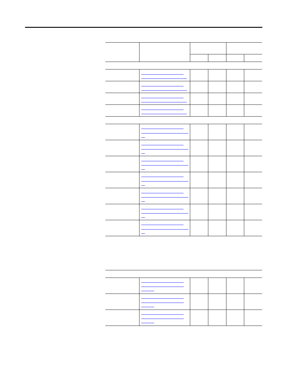
Auxiliary Input
Position - Auxiliary
Refer to Understanding the
Encoders Window on page 86
X
X
X
A
Refer to Understanding the
Encoders Window on page 86
X
X
X
X
B
Refer to Understanding the
Encoders Window on page 86
X
X
X
X
Z
Refer to Understanding the
Encoders Window on page 86
X
X
X
X
Digital Inputs
Input 1 through 8
State
Refer to Understanding the
Digital Inputs Window on page
95
X
X
Drive Enable
Refer to Understanding the
Digital Inputs Window on page
95
X
X
Home Sensor
1
Refer to Understanding the
Digital Inputs Window on page
95
X
X
Registration Sensor
1
1
Refer to Understanding the
Digital Inputs Window on page
95
X
X
Registration Sensor
2
1
Refer to Understanding the
Digital Inputs Window on page
95
X
X
Positive
Overtravel
1
Refer to Understanding the
Digital Inputs Window on page
95
X
X
Negative
Overtravel
1
Refer to Understanding the
Digital Inputs Window on page
95
X
X
1
Digital I/O on the SERCOS drives often is dedicated. The Oscilloscope uses the digital I/O variable
selections rather than the drive function selections for these signals
• Home Sensor = Digital Input 2
• Registration Sensor 1 = Digital Input 3
• Registration Sensor 2 = Digital Input 4
• Positive Overtravel = Digital Input 7
• Negative Overtravel = Digital Input 8
Digital Outputs
Output 1 through 4
State
Refer to Understanding the
Digital Outputs Window on
page 99.
X
X
Relay State
Refer to Understanding the
Digital Outputs Window on
page 99.
X
Brake
Refer to Understanding the
Digital Outputs Window on
page 99.
X
Status
(Continued)
Description
Non-SERCOS
Drive
SERCOS Drive
Scope Monitor
Scope Monitor