Rockwell Automation 2098-UWCPRG Ultraware Software User Manual User Manual
Page 261
Rockwell Automation Publication 2098-UM001G-EN-P - February 2011
263
Configuring the Kinetix 3 Drive Chapter 5
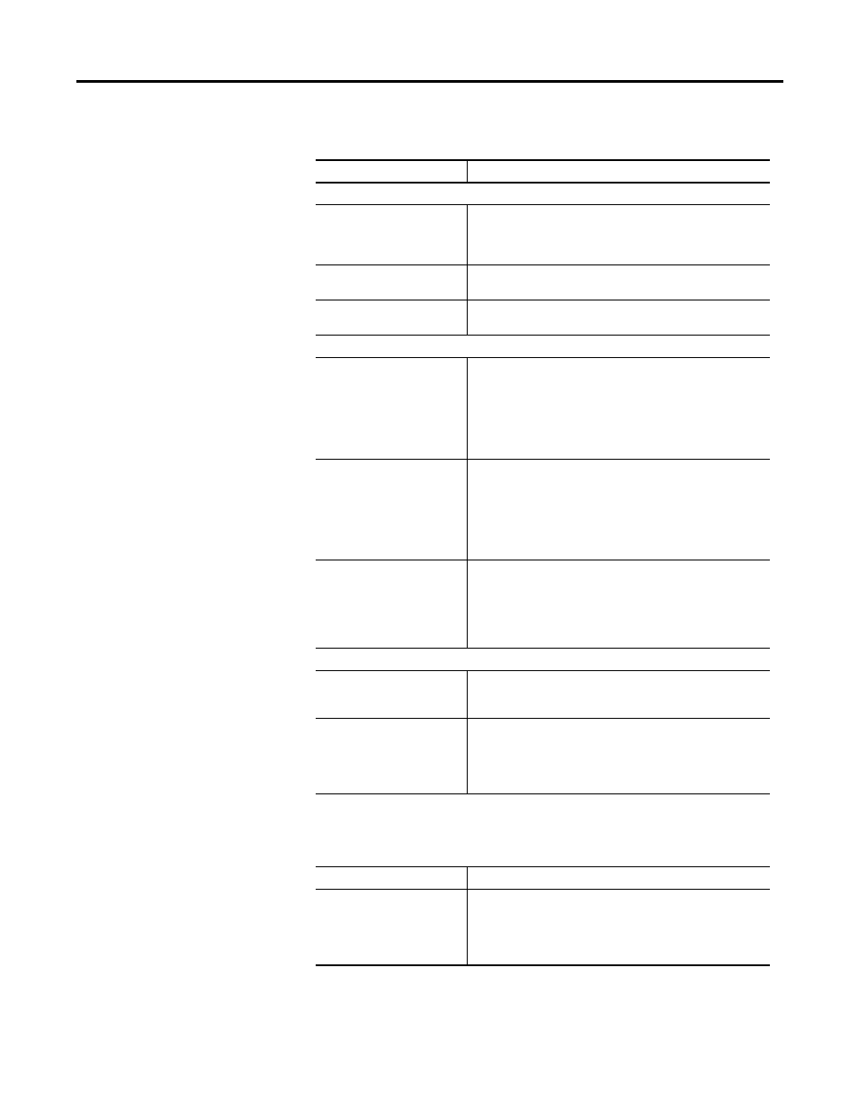
The following parameters, status, and commands apply to this window.
The following display is the default status for a Kinetix 3 drive in the Manual
Velocity Tuning window of the Tuning branch.
Parameter
Description
Manual Velocity Tuning Settings
Motor Direction
The direction in which the motor rotates during tuning:
• Bi-Directional,
• Forward Only, or
• Reverse Only.
Velocity
The the amplitude of the drive's commanded velocity step. The
range is 1…2,147,483,647 counts per second.
Time
The period of the drive's commanded velocity step. The range is
1…32,767 ms.
Velocity Regulator Gains
P
Proportional gain for the velocity loop. The P gain generates a
control signal proportional to the velocity error. The range is
0…4000.
Note: Increasing the P gain improves response time and
increases the stiffness of the system. Too high a P gain value
causes instability; too low a P gain value results in loose or
sloppy system dynamics.
I
Integral gain for the velocity loop. The I gain generates a control
signal proportional to the integral of the velocity error. The range
is 0…4000.
Note: I gain improves the steady-state velocity performance of
the system. Increasing the integral gain generally increases the
ultimate positioning accuracy of the system. However excessive
integral gain results in system instability.
D
Derivative gain value for the velocity loop. The D gain generates
a control signal proportional to measured acceleration.The
range is -1000…1000.
Note: Positive D gain reduces velocity overshoot, and negative D
gain should be used only in systems that exhibit mechanical
resonance.
Low Pass Filter
Enable
Enable or disable the drive's low pass filter. Selections are:
• Enabled
• Disabled
Bandwidth
The connected drive's low pass filter's bandwidth. This value
indicates the cutoff frequency of the low pass filter. The range is
1…992 Hz.
Note: Bandwidth reduces noise generated by encoder resolution
or mechanical resonance in the system.
Status Description
Drive Enabled
ON indicates the power stage of the drive is enabled. As a
precondition, all software and hardware enable inputs must be
active, and the drive cannot have any faults.
Note: Drive Enable has a value of 1 when ON, and a value of 0
when OFF.