Understanding the digital outputs window – Rockwell Automation 2098-UWCPRG Ultraware Software User Manual User Manual
Page 97
Rockwell Automation Publication 2098-UM001G-EN-P - February 2011
99
Configuring the Ultra3000 Drive Chapter 3
Understanding the Digital
Outputs Window
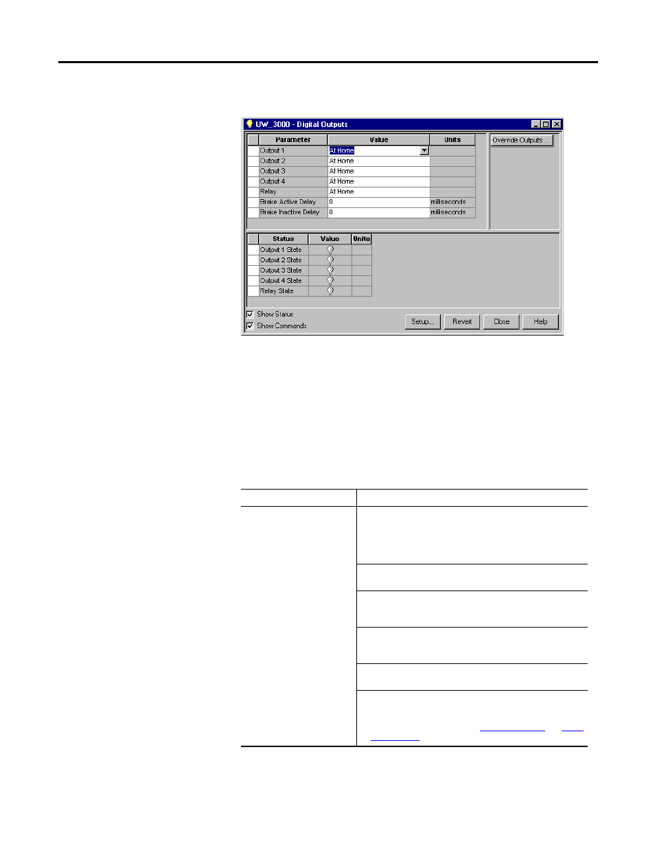
The Properties window for Digital Outputs looks like this
Use the Digital Outputs window to:
•
assign functions to digital outputs,
•
set both active and inactive brake delays,
•
monitor the status of digital outputs and the digital relay, and
•
open other windows where you can override the state of digital outputs
and the relay.
The following parameters are associated with this window:
Parameter
Description
Output 1 – 4
The functions to be assigned to each digital output (1 – 4):
Note: If multiple functions are assigned to a digital output, the
output is active if any of the assigned functions would make it
active. The assignments are logically OR'd to determine the
output state.
• At Home: An active state indicates that the position
command is equal to the Home Position.
• At Index 0 Position: An active state indicates the commanded
motor position is equal to the position defined by Index 0.
This output functions only after the axis has been homed.
• At Index 1 Position: An active state indicates the commanded
motor position is equal to the position defined by Index 1.
This output functions only after the axis has been homed.
• Axis Homed: An active state indicates that the homing
routine has completed.
• Brake: Used to control a motor brake. An active state
releases the motor brake. The Brake signal is the same as the
Drive Enabled signal, with the addition of the turn-on and
turn-off delays specified by the
Brake Active Delay
and
Brake
Inactive Delay
.