Rockwell Automation 2098-UWCPRG Ultraware Software User Manual User Manual
Page 120
122
Rockwell Automation Publication 2098-UM001G-EN-P - February 2011
Chapter 3 Configuring the Ultra3000 Drive
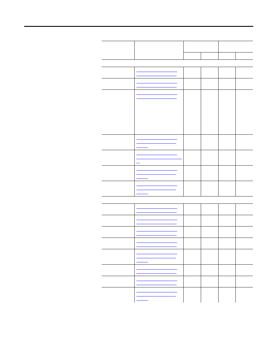
Velocity Signals
Velocity -
Command
Refer to Understanding the
Tuning Window on page 77
X
X
X
X
Velocity - Error
Refer to Understanding the
Tuning Window on page 77
X
X
X
X
Velocity - Motor
Feedback
Refer to Understanding the
Tuning Window on page 77
Note: The resolution of this
signal may be confusing when
using the Oscilloscope. See
the topic Velocity Motor
Feedback Resolution for
information on how resolution
is derived for various motor
and feedback combinations.
X
X
X
X
In Speed Window
Refer to Understanding the
Ultra3000 Drive Branch on
page 41
X
X
Integrator Inhibit
Refer to Understanding the
Digital Inputs Window on page
95
X
X
Up To Speed
Refer to Understanding the
Ultra3000 Drive Branch on
page 41
X
X
Zero Speed
Refer to Understanding the
Ultra3000 Drive Branch on
page 41
X
X
Current Signals
Current - Analog
Limit Input
Refer to Understanding the
Tuning Window on page 77
X
X
X
X
Current - Average
Refer to Understanding the
Tuning Window on page 77
X
X
X
X
Current - Command
Refer to Understanding the
Tuning Window on page 77
X
X
X
X
Current - Feedback
Refer to Understanding the
Tuning Window on page 77
X
X
X
X
Neg Current Limit
Refer to Understanding the
Ultra3000 Drive Branch on
page 41
X
X
X
X
Current - Peak -
Refer to Understanding the
Tuning Window on page 77
X
X
X
X
Current - Peak +
Refer to Understanding the
Tuning Window on page 77
X
X
X
X
Pos Current Limit
Refer to Understanding the
Ultra3000 Drive Branch on
page 41
X
X
X
X
Status
(Continued)
Description
Non-SERCOS
Drive
SERCOS Drive
Scope Monitor
Scope Monitor