Rockwell Automation 2098-UWCPRG Ultraware Software User Manual User Manual
Page 168
170
Rockwell Automation Publication 2098-UM001G-EN-P - February 2011
Chapter 4 Configuring the Ultra5000 Drive
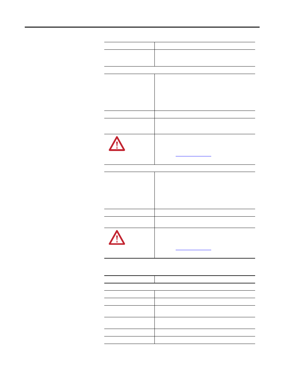
The following display is the default status for a Tuning branch of an online drive.
Kff
Velocity feedforward gain for the position loop. Must be >= 0.
Note: Kff gain reduces position following error. However high
values can cause position overshoot.
Velocity Tuning Setup
Tuning Direction
Click a tuning direction:
• Bi-Directional to tune the drive using an alternating step-
input to create alternately forward and reverse directional
motion,
• Forward Only to tune the drive using a step-input to create
only forward motion, or
• Reverse Only to tune the drive using a step-input to create
only reverse motion.
Period
The time, in seconds, the drive turns at a given velocity.
Step Size
The amplitude of the velocity input, in pulses per second (pps),
sent to the drive for the given period. In Bi-Directional tuning,
the amplitude alternates polarity (+ or - sign).
ATTENTION: Excessive tuning step profiles values
may cause uncontrolled motion. Refer to the
appropriate Hardware and Installation manual
listed in
on page 12 for tuning
details.
Position Tuning Setup
Tuning Direction
The tuning direction:
• Bi-Directional to tune the drive using an alternating step-
input to create alternately forward and reverse directional
motion,
• Forward Only to tune the drive using a step-input to create
only forward motion, or
• Reverse Only to tune the drive using a step-input to create
only reverse motion.
Period
The time, in seconds, the drive holds its present step position.
Step Size
The number of pulses the drive moves in a single direction. In Bi-
Directional tuning, the direction alternates.
ATTENTION: Excessive tuning step profiles values
may cause uncontrolled motion. Refer to the
appropriate Hardware and Installation manual
listed in
on page 12 for tuning
details.
Status
Description
Velocity Loop
Command Velocity
The command velocity input to the velocity loop.
Command Acceleration
The command acceleration input to the velocity loop.
Feedback Velocity
The feedback velocity returned from the motor to the velocity
loop.
Error
The difference between Command Velocity and Feedback
Velocity.
Error Sum
The velocity error summation used by integral gain.
Output
The generated output from the velocity loop.
Parameter
Description