Rockwell Automation 2098-UWCPRG Ultraware Software User Manual User Manual
Page 240
242
Rockwell Automation Publication 2098-UM001G-EN-P - February 2011
Chapter 5 Configuring the Kinetix 3 Drive
Click Revert to return parameter settings to the values they held when you
opened this window.
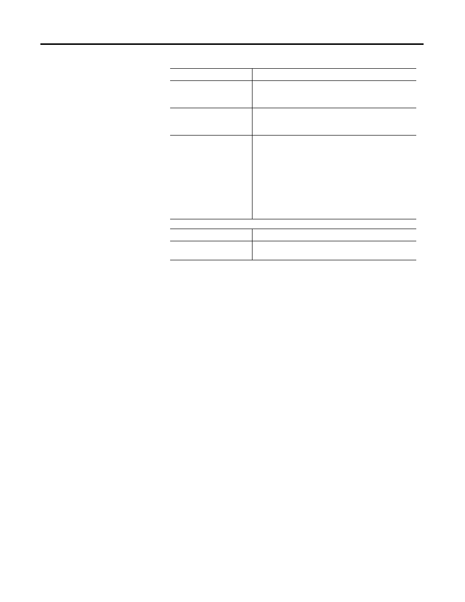
1st Gear Ratio
Specifies the 1st ratio of counts between the master input
counts and the motor encoder counts (for example 1:4).
The range of the ratio value is 1:1… 1:6,553,5:65,535.
2nd Gear Ratio
Specifies the 1st ratio of counts between the master input
counts and the motor encoder counts (for example 1:4).
The range of the ratio value is from 1:1…1:6,553,5:65,535.
Digital Filter Cut-off Frequency The cutoff frequency of the low pass digital filter applied to the
pulse command input.
• Line Driver Input:
The range is 0.525, 0.562, 0.625, 0.750, 1.000, 1.500, 1,750,
and 3.000 MHz. Default is 1.750 MHz
• Open Collector Input:
The range is 0.525, 0.562, 0.625, 0.750, 1.000, 1.500, 1,750,
and 3.000 MHz. Default is 0.625 MHz
• High Frequency Line Driver Input:
The range is 0.525, 0.562, 0.625, 0.750, 1.000, 1.500, 1,750,
and 3.000 MHz. Default is 3.000 MHz
Command
Description
Save Parameters
Saves the current working values as power-up values in flash
memory for the selected On-Line drive and all of its children.
Parameter
Description