Rockwell Automation 2098-UWCPRG Ultraware Software User Manual User Manual
Page 216
218
Rockwell Automation Publication 2098-UM001G-EN-P - February 2011
Chapter 4 Configuring the Ultra5000 Drive
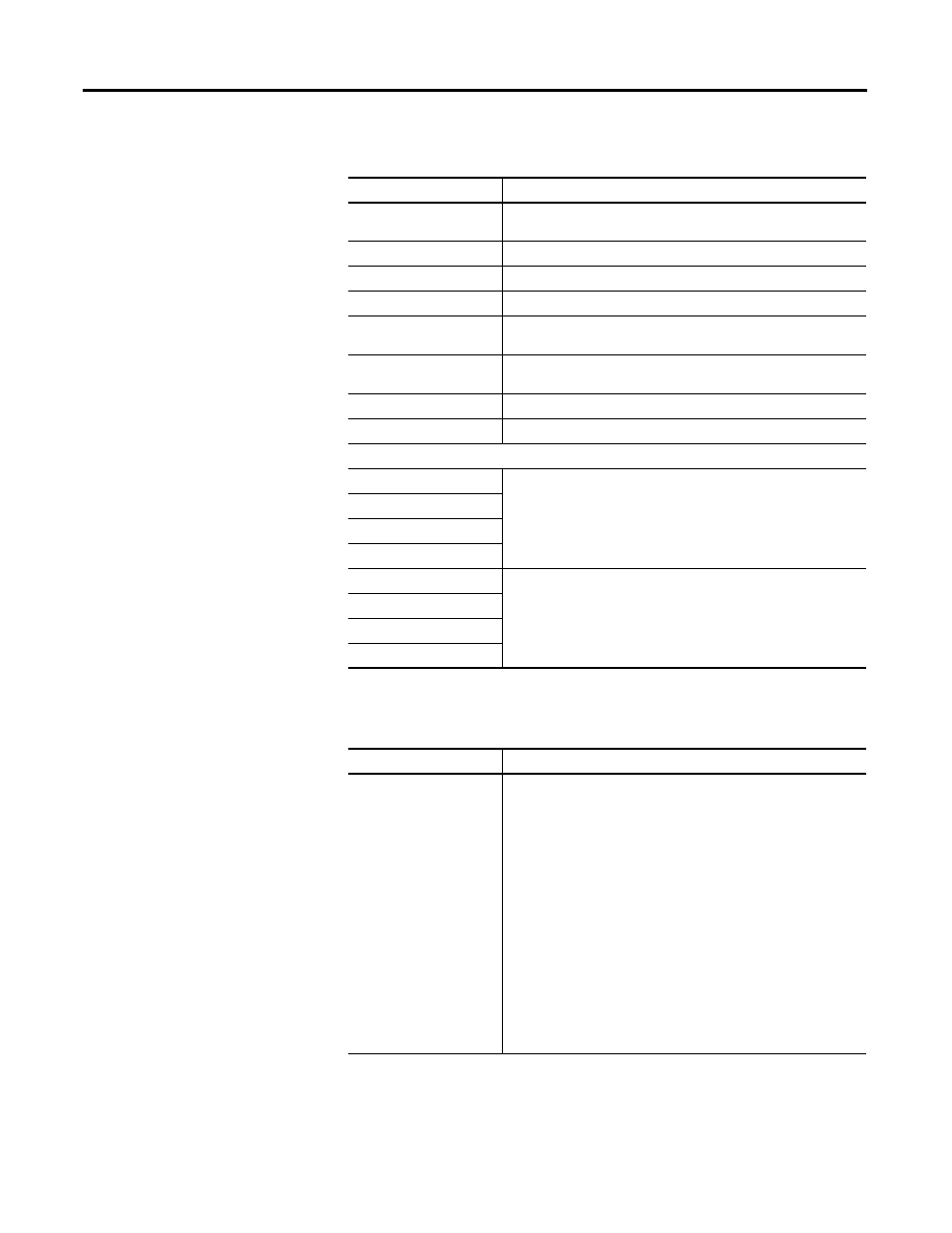
The following status is displayed by default.
The Properties window for the Service Information branch of older Ultra5000
drives, firmware revision 1.1.5 or earlier, displays these information.
Status
Description
Drive Model
The model number of the drive. (Only displayed for online drives).
This number is set at the factory.
PICS Number
A unique identifier assigned to each drive.
Firmware Version
The revision of the firmware on the drive.
Boot Firmware Version
The revision of the boot firmware on the drive.
FPGA Version
The revision of the firmware containing the FPGA image and the burn
in self test code.
Rated Current
The maximum current the drive can continuously produce without
faulting.
Peak Current
The maximum current the drive can on an intermittent basis.
Service Clock
The hours and minutes the drive has been powered-up.
Sequencer Loads
Frame Load 1
A visual graph showing the percentage of available CPU time (125
microseconds = 100%) actually used in each Frame Load (1 - 4).
Frame Load 2
Frame Load 3
Frame Load 4
Frame 1 Peak Load
The Peak Frame Load (1 - 4) since the peaks were reset.
Frame 2 Peak Load
Frame 3 Peak Load
Frame 4 Peak Load
Status
Description
Drive Type
The type of Ultra5000 drive:
• Invalid: prevents the drive from being enabled.
• 2098-IPD-005
• 2098-IPD-010
• 2098-IPD-020
• 2098-IPD-030
• 2098-IPD-050
• 2098-IPD-100
• 2098-IPD-150
• 2098-IPD-HV030
• 2098-IPD-HV050
• 2098-IPD-HV100
• 2098-IPD-HV150
• 2098-IPD-HV220
Note: the drive uses the selection to:
• decide when to signal an IPM Filter fault, and
• properly scale the feedback from the power stage of the drive. The
output of the velocity regulator stage of the drive is limited by the
selected drive type.