Rockwell Automation 2098-UWCPRG Ultraware Software User Manual User Manual
Page 140
142
Rockwell Automation Publication 2098-UM001G-EN-P - February 2011
Chapter 4 Configuring the Ultra5000 Drive
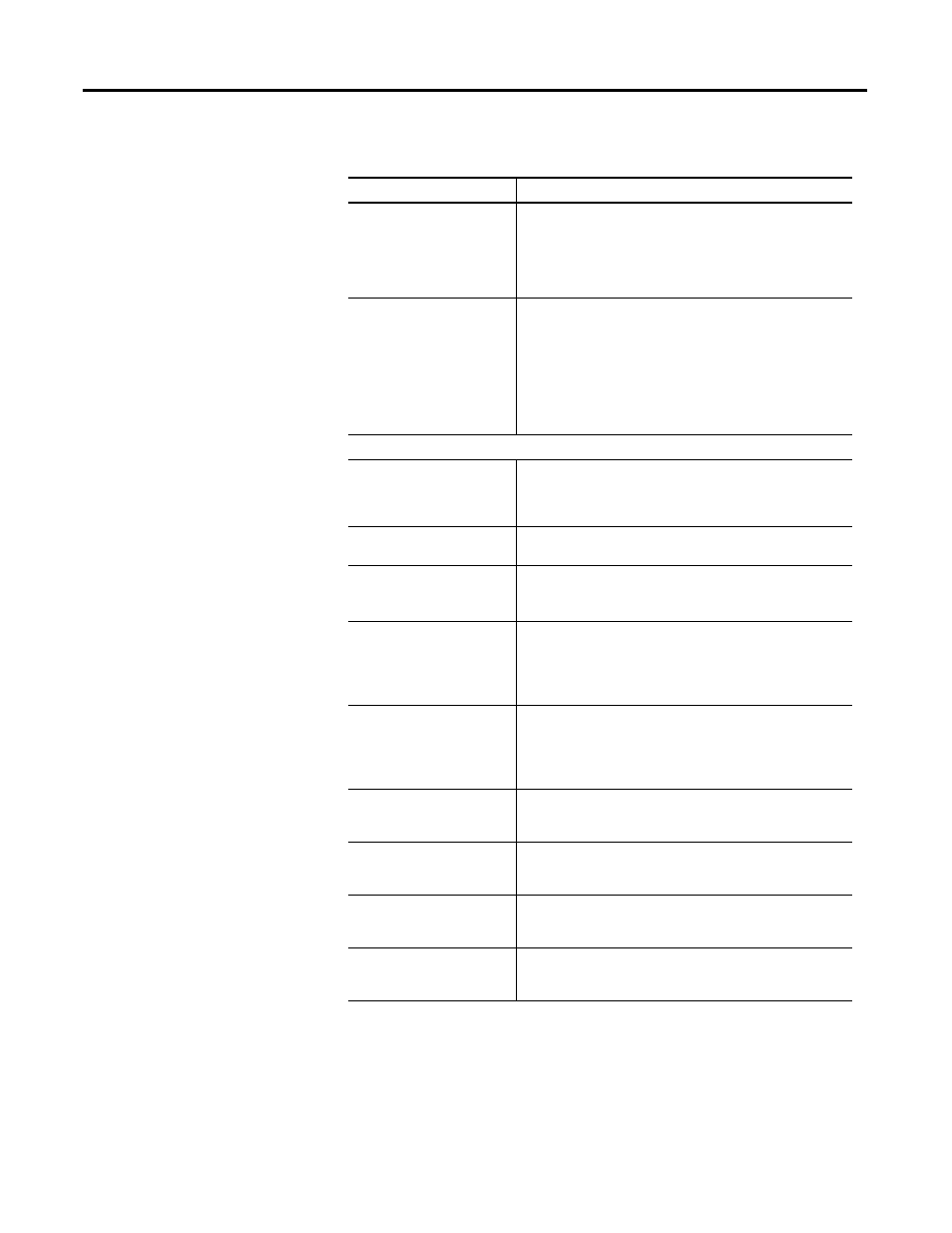
The following parameters apply to the Ultra5000 Drive branch.
Parameter
Description
Name
The name of the selected Ultra5000 drive. It must:
• be at least one, but not more than eight, characters in length,
• be unique within its branch of the tree, and
• not contain a space or backslash (\), forward slash (/), colon
(:), asterisk (*), question mark (?), double quote ("), greater
than symbol (>), less than symbol (<) or pipe (|).
Digital I/O Type
Click the digital I/O type:
• Sinking: Digital Inputs should be connected to ground, so
current flows from the drive when the input is ON. Digital
Outputs should be connected to a 24 volt power supply, so
current flows into the drive when the output is ON.
• Sourcing: Digital Inputs should be connected to a 24 volt
power supply, so current flows into the drive when the input
is ON. Digital Outputs should be connected to ground, so
current flows from the drive when the output is ON.
Position Limits
Deceleration Rate
When a limit is detected, the drive uses this deceleration rate to
bring the axis to a stop, unless doing so would violate the Max
Decel Distance (see below). If necessary to stay within the Max
Decel Distance, the drive calculates a greater deceleration rate.
Max Decel Distance
When a limit is detected, the drive brings the axis to a stop
within this distance.
Soft Limits Enable
Set this to True to enable detection of soft limit violations.
The Position Limits (see below) must also be enabled for soft
limit violations to be detected.
Hard Limits Enable
Set this to True to enable detection of hard limit violations.
The Position Limits (see below) must also be enabled for hard
limit violations to be detected. The inputs to use for positive and
negative hard limits must be set (see below) for the hard limits
to be detected.
Motor Limits Enable
Set this to True to enable detection of motor integral limit
violations.
The Position Limits (see below) must also be enabled for motor
limit violations to be detected. The motor limits only work when
using a motor that supports integral limits.
Positive Soft Limit
The position, in counts, when a positive soft limit violation is
detected by the drive. This is the point where the drive begins
decelerating the axis.
Negative Soft Limit
The position, in counts, when a negative soft limit violation be
detected by the drive. This is the point where the drive begins
decelerating the axis.
Positive Hard Limit
The selected digital input to use to indicate a positive hard limit
violation. The drive begins decelerating the axis when the input
becomes active. Select:
Negative Hard Limit
The selected digital input to use to indicate a negative hard limit
violation. The drive begins decelerating the axis when the input
becomes active. Select: