Rockwell Automation 2098-UWCPRG Ultraware Software User Manual User Manual
Page 211
Rockwell Automation Publication 2098-UM001G-EN-P - February 2011
213
Configuring the Ultra5000 Drive Chapter 4
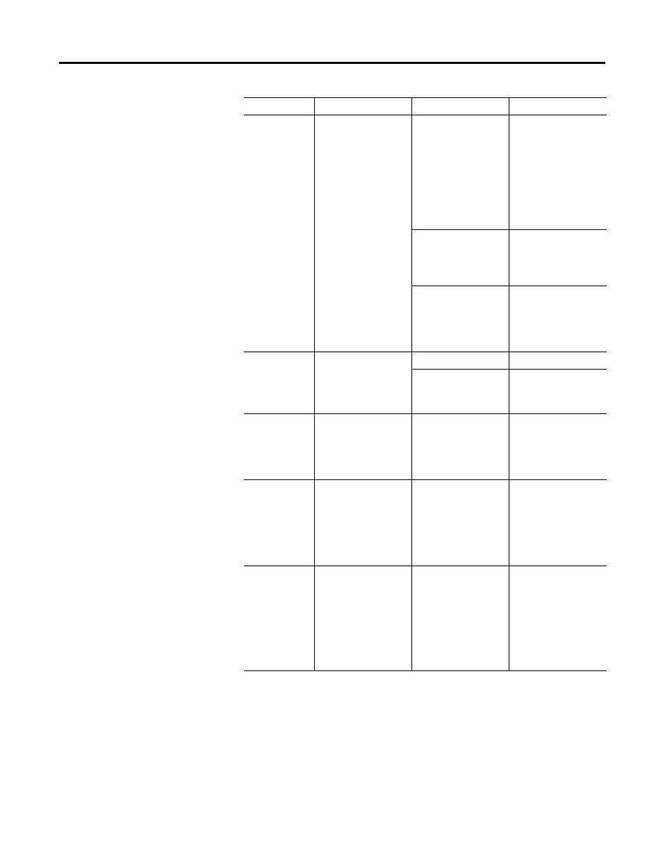
10: Bus
Overvoltage
Output short circuit.
Disconnect the power
line from the drive and
then do continuity check
from the positive and
negative poles of the DC
Bus to each of the motor
output phases U,V, and
W. If a continuity exists,
check for wire fibers
between terminals, or
send drive in for repair.
Motor cabling wires
shorted together.
Disconnect motor power
cables from the drive. If
faults stop, then either
replace cable or try to
find the short.
Internal motor winding
short circuit.
Verify by disconnecting
motor from drive and
then try to turn by hand.
If difficult to turn by
hand, the motor needs to
be repaired or replaced.
11: Illegal Hall
State
ON indicates there is a
problem with the motor's
Hall Effect sensors.
Incorrect phasing.
Check the Hall phasing.
Incorrect wiring
• Verify the Hall wiring.
• Verify power supply to
encoder.
17: User Current
ON indicates the User
Current Fault level, input
above, has been
exceeded.
User-specified average
current level exceeded.
• Increase User Current
Level and Time to a
less restrictive
setting.
• Increase motion time
interval.
18: Overspeed
ON indicates the motor
speed has exceeded
125% of maximum rated
speed.
Motor exceeded 125% of
the-specified maximum
rated speed.
• Check cables for
noise.
• Check motor wiring;
• Retune drive & motor
combination.
• Use an actual
oscilloscope to check
encoder phasing.
19: Following
Error
ON indicates the
Following Error Limit, set
above, has been
exceeded.
Position error limit
exceeded.
• Retune the drive,
starts by setting the
feed forward gain to
100%.
• Increase the Following
Error Limit, above.
• If in Follower Mode,
increase the Slew
Limit (in the Follower
window).
Status
Description
Possible Cause
Suggested Action