Rockwell Automation 2098-UWCPRG Ultraware Software User Manual User Manual
Page 46
48
Rockwell Automation Publication 2098-UM001G-EN-P - February 2011
Chapter 3 Configuring the Ultra3000 Drive
The following status is displayed by default for an Ultra3000 drive in the On-
Line Drives branch of the Workspace window.
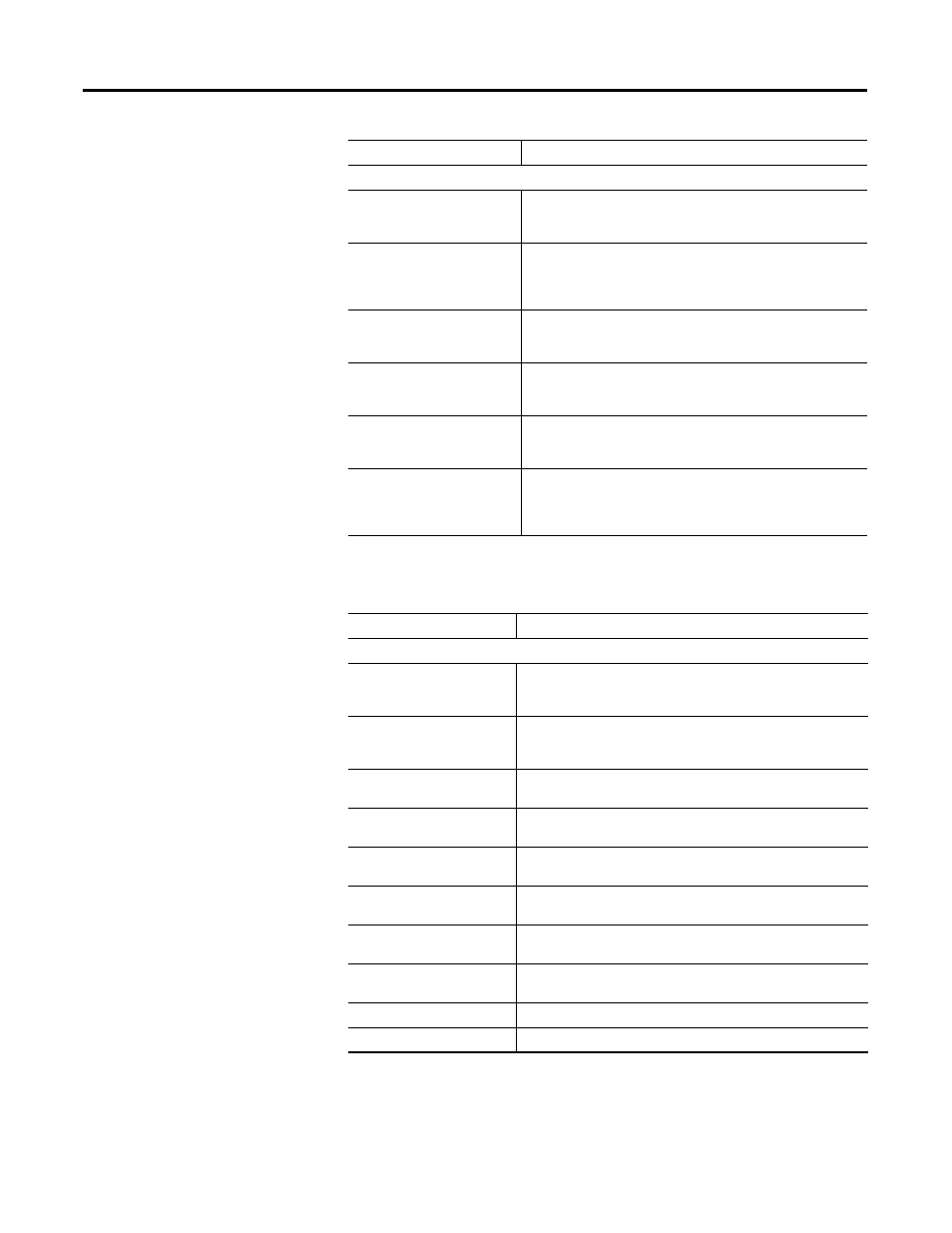
Auxiliary Encoder Units
Velocity Label
When User is selected for Displayed Units, this is the user-defined
label for velocity values relating to the auxiliary encoder. Limited
to 16 characters in length.
Velocity Scale
When User is selected for Displayed Units, this is the user-defined
conversion factor used to convert velocity values, relating to the
auxiliary encoder, into user units. In counts per second per user
unit.
Position Label
When User is selected for Displayed Units, this is the user-defined
label for position values relating to the auxiliary encoder. Limited
to 16 characters in length.
Position Scale
When User is selected for Displayed Units, this is the user-defined
conversion factor used to convert position values, relating to the
auxiliary encoder, into user units. In Counts per user unit.
Acceleration Label
When User is selected for Displayed Units, this is the user-defined
label for acceleration values relating to the auxiliary encoder.
Limited to 16 characters in length.
Acceleration Scale
When User is selected for Displayed Units, this is the user-defined
conversion factor used to convert acceleration values, relating to
the auxiliary encoder, into user units. In counts per second
squared per user unit.
Status
Description
Note: All ON status have a value of 1; all OFF status have a value of 0.
Drive Enabled
ON indicates the power stage of the drive is enabled. As a
precondition, all software and hardware enable inputs must be
active, and the drive cannot have any faults.
In Position
ON indicates position error has been less than the In Position Size
setting for longer than the In Position Time setting, and the speed is
less than the Zero Speed setting.
In Position Window
ON indicates position error has been less than the In Position Size
setting for longer than the In Position Time setting.
Up To Speed
ON indicates motor velocity feedback is greater than the Up To
Speed setting.
In Speed Window
ON indicates motor velocity feedback falls within the range of
programmed velocity +/- the Speed Window value.
Zero Speed
ON indicates the motor velocity feedback value is less than the
Zero Speed setting.
Pos Current Limit
ON indicates the current of the drive is limited by the Positive
Current Limit, above.
Neg Current Limit
ON indicates the current of the drive is limited by the negative
Current Limit, above.
Bus Power
ON indicates power is applied to the DC Bus.
Bus Voltage
The present measure of Bus voltage.
Parameter Description