Rockwell Automation 2098-UWCPRG Ultraware Software User Manual User Manual
Page 85
Rockwell Automation Publication 2098-UM001G-EN-P - February 2011
87
Configuring the Ultra3000 Drive Chapter 3
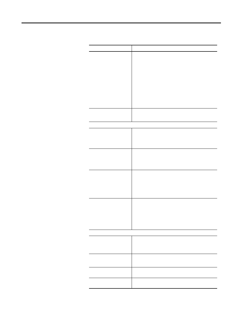
This window has these parameters:
Parameter
Description
Motor Encoder Interpolation
The amount of interpolation to be used with sine/cosine
encoders:
• x4
• x8
• x16
• x32
• x64
• x128
• x256
• x512
• x1024
For example, if a Stegmann encoder outputs 1024 cycles per
revolution and Encoder interpolation is set to x256, the drive will
use 262144 (1024 x 256) counts per revolution as the effective
feedback.
Position Feedback Source
The source for position loop feedback:
• Motor Encoder
• Auxiliary Encoder
Motor Encoder Output
Output Signal
Specifies the type of encoder output from the drive:
• Buffered: The encoder input is passed through the drive
directly, without interpolation or division.
• Divided: The encoder input is divided and output. See Divider.
• Interpolated: The interpolated encoder counts are output.
Divider
Type the amount of division used for generating output encoder
signals. For example, if the Divider is set to 4, the encoder
output frequency is 1/4th the encoder input frequency.
Note: This parameter is active only if Divided is selected as the
Output Signal.
Maximum Output Frequency
The encoder output frequency limit:
• 500 kHz
• 1 MHz
• 4 MHz
• 8 MHz
Note: This parameter is active only if Divided or Interpolated is
selected as the Output Signal.
Marker Output Gating
Permits the drive to produce and use a more precise marker
signal. The options are:
• Not Gated: The drive uses and outputs the normal marker
input as received from the encoder.
• Gated with A and B: The marker output of the drive is the
logical And of the marker input from the encoder and the A
and the B inputs. This produces a more precise marker signal
for homing.
Auxiliary Encoder
Encoder Ratio (Load:Motor)
Type the ratio of encoder counts between the load encoder and
the motor encoder.
Note: This parameter is active only if the Position Feedback
Source is selected to be the Auxiliary Encoder.
Type
The type of auxiliary encoder:
• Rotary
• Linear
Lines/Revolution
Encoder lines per revolution.
Note: This parameter is visible only if the Type is Rotary.
Lines/Meter
Encoder lines per meter of travel.
Note: This parameter is visible only if the Type is Linear.