Rockwell Automation 2098-UWCPRG Ultraware Software User Manual User Manual
Page 283
Rockwell Automation Publication 2098-UM001G-EN-P - February 2011
285
Configuring the Kinetix 3 Drive Chapter 5
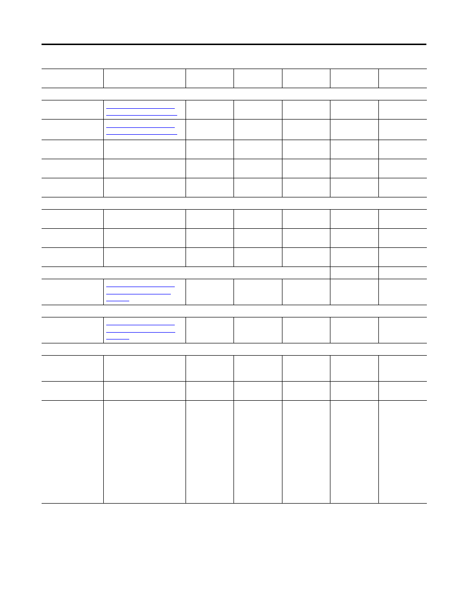
Current Signals
Current - Command
Refer to Understanding the
Tuning Window on page 253
X
X
X
X
X
Current - Feedback
Refer to Understanding the
Tuning Window on page 253
X
X
X
U Phase Current
The current through the U
phase of the motor
X
X
V Phase Current
The current through the V
phase of the motor
X
X
W Phase Current
The current through the W
phase of the motor
X
X
Encoder Signals
S1
Hall input S1 of the motor
encoder
X
S2
Hall input S2 of the motor
encoder
X
S3
Hall input S3 of the motor
encoder
X
Digital Inputs
Input 1…7 State
Refer to Understanding the
Digital Inputs Window on
page 267
X
X
X
X
Digital Outputs
Output 1…3 State
Refer to Understanding the
Digital Outputs Window on
page 271
X
X
X
X
Power Status
Shunt Power Limit
Ratio
Reports the percent of the
shunts rated capacity currently
being used.
X
X
X
X
X
Instantaneous Shunt
Power
Power dissipated in the
internal shunt resistor.
X
X
X
X
X
Output Power Limit
Ratio
Reports the accumulated
usage of the drive's capability
to operate above its rated
output power.
The drive may safely produce
slightly more than the rated
output power for a period of
time. If this value reaches
100%, the drive produces fault
104, Continuous Power
Overload Fault. This value
decreases to zero when the
drive is operating at less than
rated output power.
X
X
X
X
X
Status
Description Oscilloscope
Input Trigger
Oscilloscope
Output Trigger
Monitor Analog
Output
Signal
Fault Detail
Channel