Rockwell Automation 2098-UWCPRG Ultraware Software User Manual User Manual
Page 255
Rockwell Automation Publication 2098-UM001G-EN-P - February 2011
257
Configuring the Kinetix 3 Drive Chapter 5
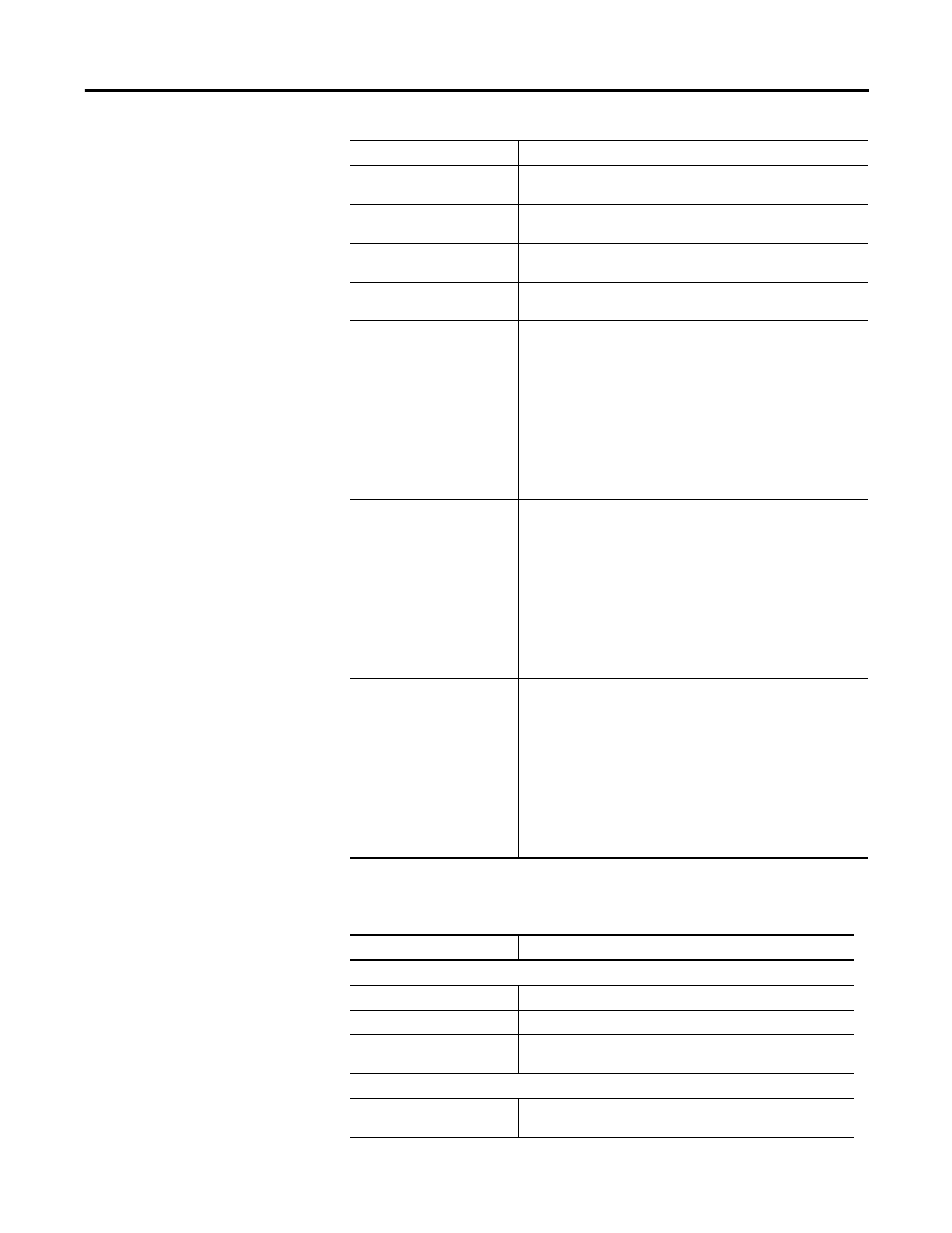
The following status is displayed by default for the Tuning branch of an online
drive.
Delay Time of Gain Switching
This value indicates the delay time when changing form from 2nd
gain to 1st gain in 0.2 ms units.
Level of Gain Switching
This value indicates the switching level when changing form from
2nd gain to 1st gain.
Hysteresis of Gain Switching
This value indicates the hyteresis width to be operated above/
below the switching level.
Position Gain Switching Time
This value indicates the step by step switching time to tho position
gain while changing the 1st gain to 2nd gain in 0.2 ms units.
2nd Regulator Gains
The drive uses these tuning values when the Alternate Gain Select
function is assigned to an input, and that input is active.
• P: See the P Gain description in the Main Velocity Regulator
Gains section above.
• Integrator Time: See Integrator Time description in the Main
Velocity Regulator Gains section, above.
• Low Pass Bandwidth(VReg): See Low Pass Filter Bandwidth
description in the Main Velocity Regulator Gains section, above.
• Kp: See Kp Gain description in the Main Position Regulator
Gains section, above.
• Low Pass Bandwidth(IReg): See Low Pass Filter Bandwidth
description in the Main Current Regulator Gains section, above.
3rd Regulator Gains
The drive uses these tuning values when the Alternate Gain Select
function is assigned to an input, and that input is active.
• P: See the P Gain description in the Main Velocity Regulator
Gains section above.
• Integrator Time: See Integrator Time description in the Main
Velocity Regulator Gains section, above.
• Low Pass Bandwidth(VReg): See Low Pass Filter Bandwidth
description in the Main Velocity Regulator Gains section, above.
• Kp: See Kp Gain description in the Main Position Regulator
Gains section, above.
• Low Pass Bandwidth(IReg): See Low Pass Filter Bandwidth
description in the Main Current Regulator Gains section, above.
4th Regulator Gains
The drive uses these tuning values when the Alternate Gain Select
function is assigned to an input, and that input is active.
• P: See the P Gain description in the Main Velocity Regulator
Gains section above.
• Integrator Time: See Integrator Time description in the Main
Velocity Regulator Gains section, above.
• Low Pass Bandwidth(VReg): See Low Pass Filter Bandwidth
description in the Main Velocity Regulator Gains section, above.
• Kp: See Kp Gain description in the Main Position Regulator
Gains section, above.
• Low Pass Bandwidth(IReg): See Low Pass Filter Bandwidth
description in the Main Current Regulator Gains section, above.
Status Description
Velocity Loop
Command Velocity
The commanded motor velocity.
Feedback Velocity
The actual motor velocity.
Error
The difference between the commanded motor velocity and the
actual motor velocity.
Position Loop
Master Position
The motor position command before scaling by the Gear Ratio,
in units of master counts.
Parameter Description