Control panel (only type mtr-dci-...-h2) 4-7, Menu command description, Tab. 4/2: menu commands (overview) – Festo Электромотор MTR-DCI User Manual
Page 79
4. Control panel (only type MTR-DCI-...-H2)
4-7
Festo P.BE-MTR-DCI-CO-EN en 1209a
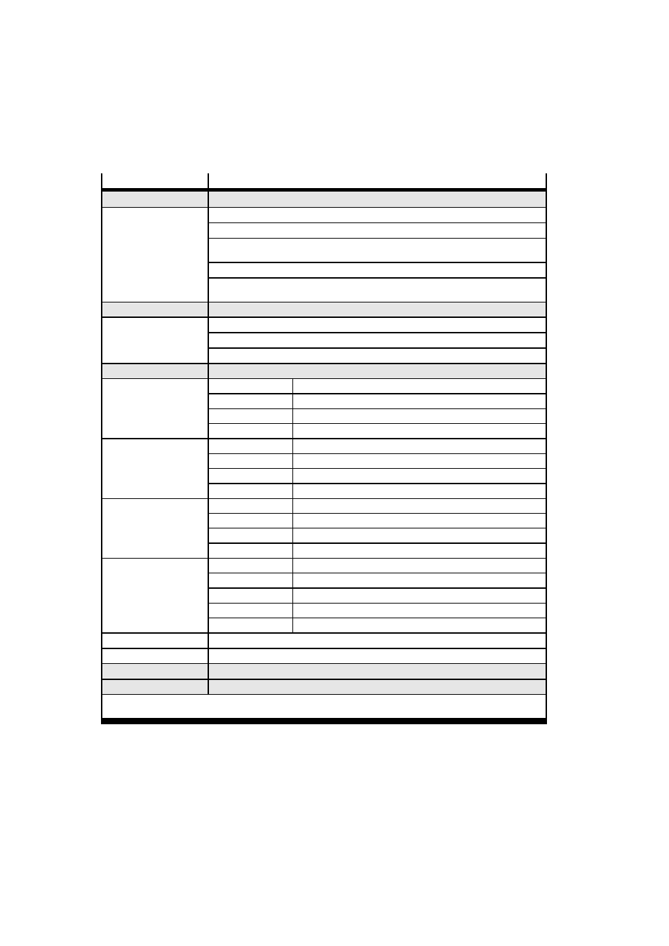
Menu command
Description
}
Diagnostic
Displays the system data and the currently effective settings (see chapter 4.3)
} Pos. set table
Displays the position record table
} Axis parameters
Displays axis parameters and data
} System
paramet.
Displays system parameters and system data
} CAN Bus Diag
Displays data for CANopen diagnosis
} Software
information
Displays the operating system version (firmware)
}
Positioning
1) 2)
Reference run and positioning runs for testing the position records (see chapter 4.4)
} Move posit. set
Start positioning run “Position set”
} Demo posit. tab
Start positioning run “Position set table”
} Homing
Start the reference run
}
Settings
1) 2)
Selection of the drive, parametrizing, programming the position sets ... (see chapter 4.5)
} Axis type
} Type DMES-...
Valve actuator DMES-...
} Type DNCE-...
Electric cylinder DNCE-...
} Rotation drive
Rotation axis with stop
} User config
Any linear drive
} Axis parameters
} Zero point
3)
Offset axis zero point
} Abs.min.pos
3)
Stroke limitation: Software end position, negative
} Abs.max.pos
3)
Stroke limitation: Software end position, positive
} SAVE...
Save parameters in EEPROM
} Homing
parameter
} Homing method
Select referencing (homing) method (stop, software limit switch...)
} Velocity v_sw
Positioning speed for searching for the reference point
} Velocity v_s0
Positioning speed for moving to the axis zero point
} SAVE...
Save parameters in EEPROM
} Position set
} Position nr.
Number of the position record (0...14)
} Pos set mode
Absolute or relative positioning
} Position
3)
Target position of the position set
} Velocity
Positioning speed of the position set
} SAVE...
Save parameters in EEPROM
} Password edit
Set up a local password with 3 figures for the control panel (see chapter 4.5)
} CAN parameter
Setting the field bus parameter
}
HMI control
1)
Presetting the device control via the control panel (see chapter 4.6)
}
LCD adjustment
Rotate the display in steps of 90°
1)
If necessary password protection
3)
Teach mode
2)
Controller interface must be deactivated, see [HMI] control] :HMI = on
Tab. 4/2: Menu commands (overview)