2 signs and directions – Festo Электромотор MTR-DCI User Manual
Page 39
1. System overview
1-17
Festo P.BE-MTR-DCI-CO-EN en 1209a
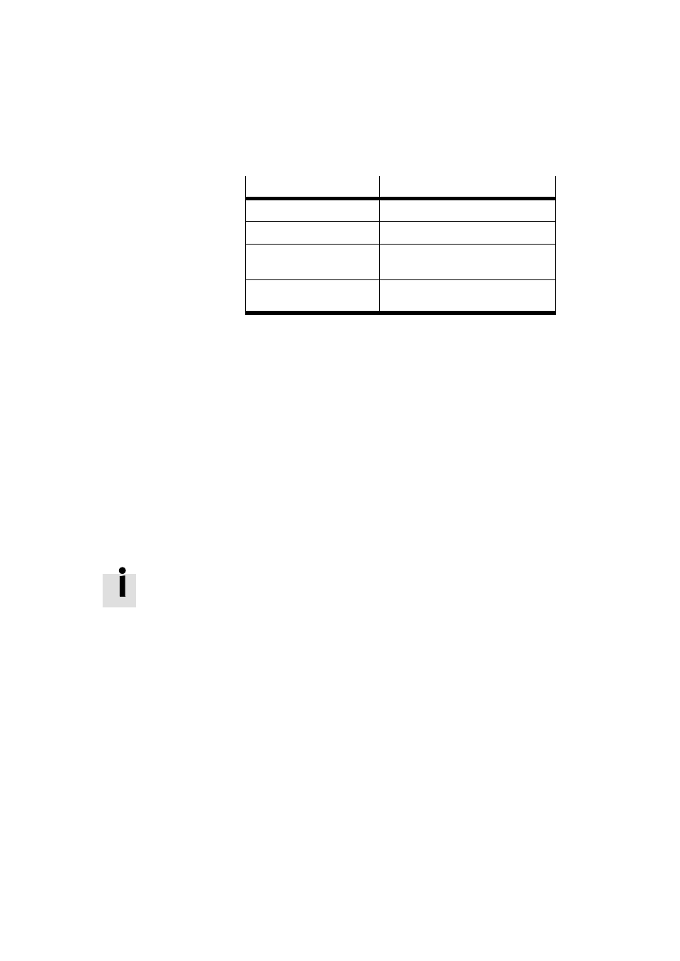
Reference point
Calculating specification
Axis zero point
AZ
= REF
+ a
Project zero point
PZ
= AZ
+ d
= (REF
+ a) + d
Lower software end
position
LSE
= AZ
+ b
= (REF
+ a) + b
Upper software end
position
USE
= AZ
+ c
= (REF
+ a) + c
Tab. 1/3: Calculating specifications for the measuring reference system with incremental
measuring systems
1.6.2
Signs and directions
All offsets and position values are vectors (with sign). The +/-
direction of the vectors can be assigned to the direction of
rotation of the motor shaft (view towards the motor shaft).
The factory setting is “+” for rotation in a clockwise direction;
“-” for rotation in an anti-clockwise direction. The assignment
can be reversed on the control panel (see chapter 4.5.2) or
via the FCT. This can be advantageous if you are using angled
or toothed belt drives. Afte reversal new homing (reference
travel) is then required.
The direction in which the work load moves depends on the
gear, the spindle type (left/right-hand turning), the sign for
the position specifications (+/-) and the work direction set.