A.2 accessories – Festo Электромотор MTR-DCI User Manual
Page 206
A. Technical appendix
A-6
Festo P.BE-MTR-DCI-CO-EN en 1209a
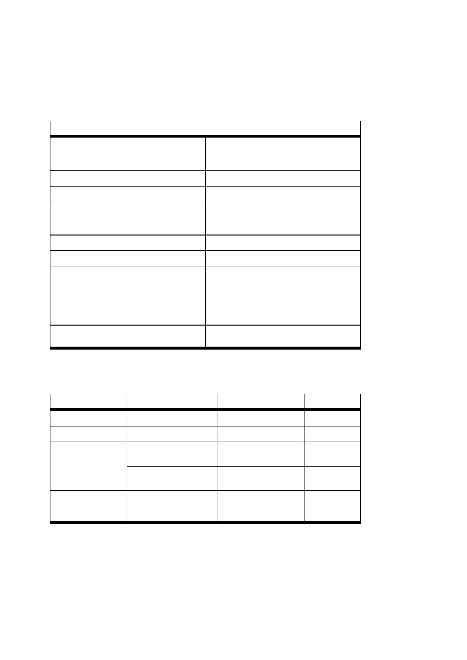
CANopen data
Design
– Physical Layer
– Data Link Layer
as per ISO 11898 (corresponding to DS 102)
as per CAN specification 2.0
CAN protocol
as per DS 301 and CiA 402
Manufacturer ID
29 (0x1D)
Profile ID (device type)
Dependent on data profile:
– CiA 402:
131474
(0x00420192)
– FHPP:
301
(0x0000012d)
Address range (node ID).
1 ... 127
Transmission rate
20, 50, 100, 125, 250, 500, 800 and 1000 kBit/s
Interface
– Plug
– Electrical isolation depending on parameteriz-
ation (see sections 3.3.2, 4.5 and 5.2.7)
– Integrated bus termination
D-Sub, 9-pin
Parameter “CAN Voltage Supply”:
– internal: No electrical isolation (default)
– external: Electrical isolation
No
Cable type
Dependent on cable length and fieldbus bit rate,
see controller manual or DS 102.
A.2
Accessories
Connection
Accessories
Designation
Length [m]
Voltage supply
Power supply cable
KPWR-MC-1-SUB-9HC-...
2.5 / 5 / 10
Serial interface
Programming cable
KDI-MC-M8-SUB-9-...
2.5
Reference switch
Switch, magnetic
Switch, inductive
SMT-8M-...-M8D
SIEN-...-M8B-...
–
Connecting cable with
screw-type lock
KM8-M8-GSGD....
0.5 / 1 / 2 / 5
Field bus connection
incl. logic power
supply
Field bus adapter (IP54)
FBA-CO-SUB-9-M12
–