2 load and logic voltages – Festo Электромотор MTR-DCI User Manual
Page 60
3. Installation
3-8
Festo P.BE-MTR-DCI-CO-EN en 1209a
3.3.2
Load and logic voltages
Load voltage
The power electronics and the motor are supplied with direct
current via the voltage connection.
•
Use the power supply cable KPWR-MC-1-SUB-9HC-... (max
length of 10 m).
•
Use a closed-loop controlled power unit with high output
reserve and external fuse for the load voltage supply.
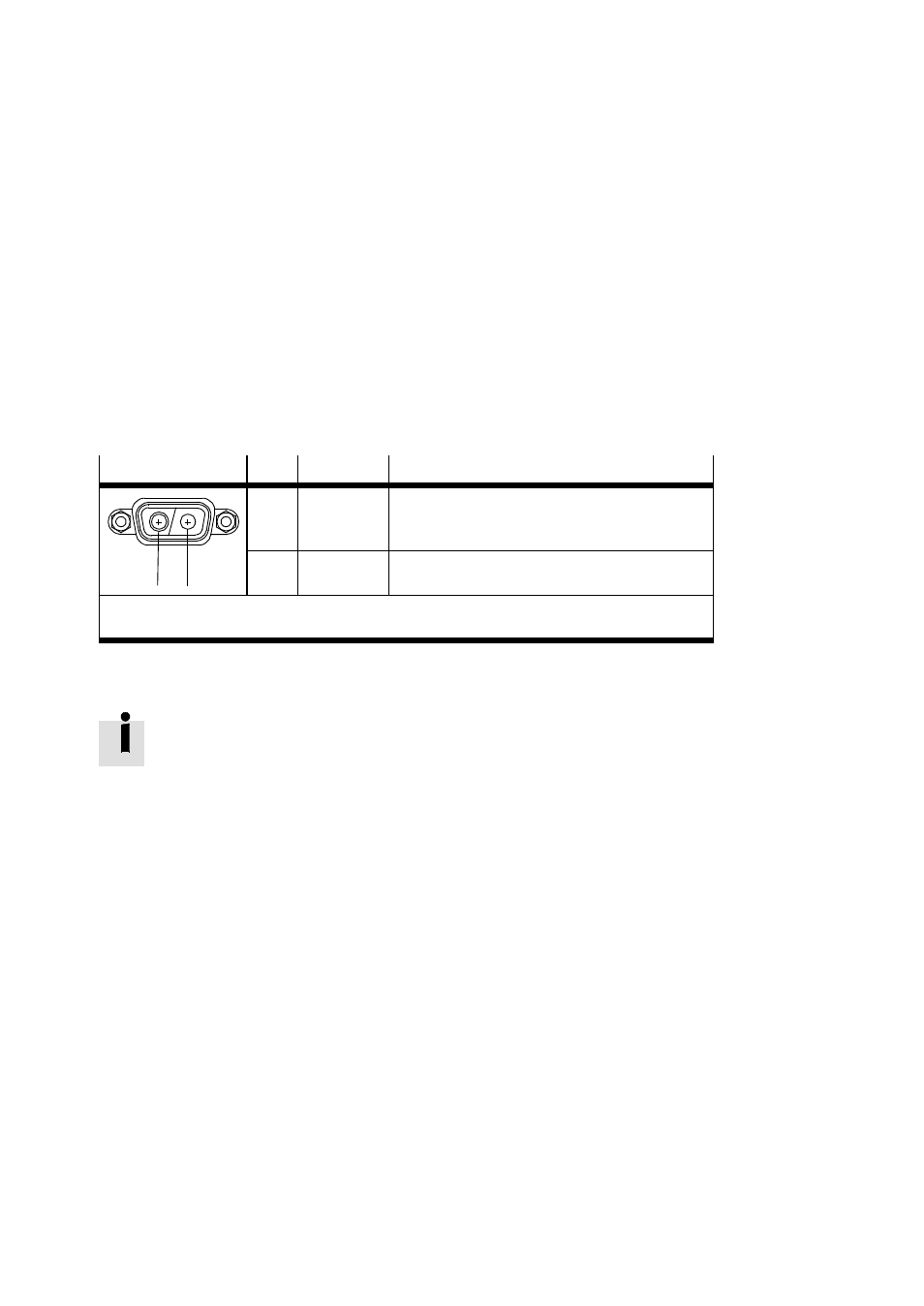
Plug
Pin
Colour
1)
Description
A1
A2
A1
black (1)
MTR-DCI-32/42/52:
MTR-DCI-62:
POWER +24 VDC
POWER +48 VDC
A2
black (2)
MTR-DCI-32/42/52/62:
POWER GND
2)
1)
Cable colours with power supply cable KPWR-MC-1-SUB-9HC-...
2)
Do not connect GND with the housing, screening or functional earth (FE)!
Tab. 3/3: Connecting the power supply to the motor unit
Closed-loop controlled DC motors have a much higher current
consumption during the switch-on or starting torque than in
rated operation. These consumers cause a brief overloading
of the power supply or a short circuit.
Power supply units with U/I output curve continue to provide
the full output current (at reduced output voltage) even in the
event of a higher load or short circuit.
With power units with additional output reserve (power
boost), the output voltage remains constant even during
overload. Power units with U/I characteristic curve and power
reserve are therefore optimally suited for universal industrial
use.