Festo Электромотор MTR-DCI User Manual
Page 260
B. Reference – Festo Handling and Positioning Profile (FHPP)
B-42
Festo P.BE-MTR-DCI-CO-EN en 1209a
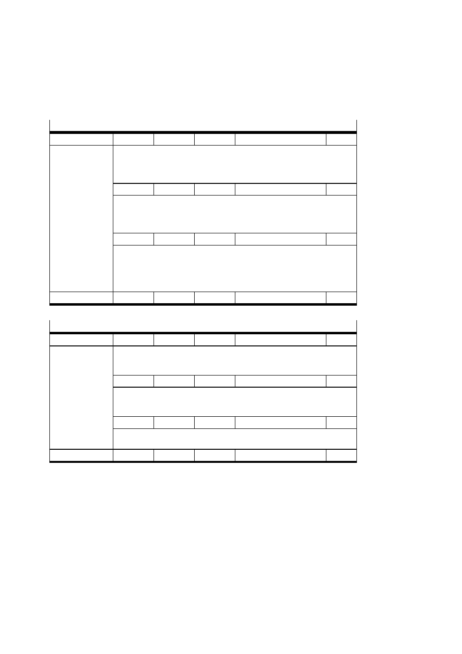
Gear Ratio
FHPP
1002
1, 2
Array
uint32
rw
Description
Ratio of the internal motor revolutions to the external revolutions of the drive
shaft of the MTR-DCI. The values are set fixed depending on the internal gear
(see type plate of the MTR-DCI).
Gear ratio = motor revolutions / spindle revolutions
Motor revolutions 1002
1
uint32
rw
Internal motor revolutions (gear ratio - counter)
Gear G7: Fixed: 27 (0x1B)
Gear G14: Fixed: 3969 (0xF81)
Gear G22: Fixed: 1710 (0x6AE)
Shaft revolutions 1002
2
uint32
rw
External revolutions of the drive shaft of the MTR-DCI
(gear ratio – denominator).
Gear G7: Fixed: 4 (0x04)
Gear G14: Fixed: 289 (0x121)
Gear G22: Fixed: 77 (0x4D)
CANopen / CI
6091h
01h, 02h
Array
uint32
rw
Feed Constant
FHPP
1003
1, 2
Array
uint32
rw
Description
The feed constant specifies the path (= feed) which the slide traverses when
the drive shaft of the linear axis makes one revolution (feed constant = shaft
revolution).
Feed 1003
1
uint32
rw
Specification of feed (feed constant - counter) in [μm].
When known axis types are selected on the control panel or in FCT, the value
is entered automatically.
Shaft revolutions 1003
2
uint32
rw
Feed constant - denominator.
Fixed: 1 (0x01)
CANopen / CI
6092h
01h, 02h
Array
uint32
rw