IAI America RCM-101-USB User Manual
Page 96
6. Initial Setting and Position Data Editing for SEP
Controllers
84
(2) Current position/alarm code
The current position of the axis you are editing (unit: mm) and the associated alarm code, if any, are shown.
Fig. 6.17 Current Position/Alarm Code
For emergency stop, “Emergency stop” is displayed on the current position and alarm code displaying part.
Fig. 6.18 Emergency Stop Indication
When motor voltage lowers, “Motor volt. low” is displayed on the current position and alarm code displaying
part.
Fig. 6.19 Motor Voltage Low Indication
* When the motor voltage low is displayed, it means a state that the motor drive power is shut off.
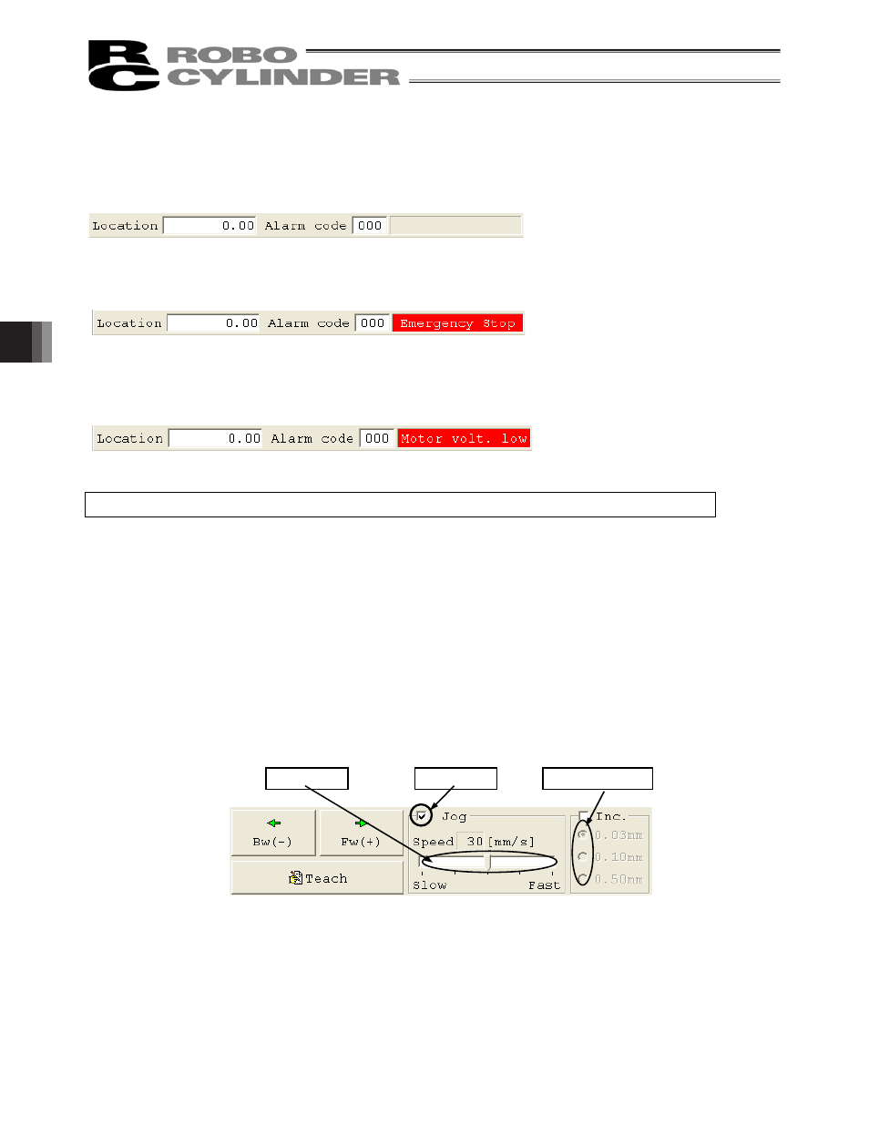
(3) Jogging/Inching operation controls
Select
Jog or Inc. (by adding a check mark to the corresponding checkbox) and use the [Fw (+)] [Bw (-)]
buttons to move the axis.
Select the jogging speed from “1,” “10,” “30,” “50” and “100” [mm/sec] using the track bar.
In the inching mode, select the feed pitch from “0.03,” “0.10” and “0.50” [mm] using the applicable radio button.
A click will move the axis by the specified pitch, while holding down the mouse button will cause the axis to jog
at 1 mm/sec after 2 second. If the mouse button is held continuously, the jogging speed will increase from
“10” to “30” and to “100” [mm/sec] every second.
If home return has been completed, clicking
Teach will load the current position to the point data input area.
* In the position data input area, the loaded data will be input to the row where the cursor is located. Check the
cursor position before clicking
Teach.
Fig. 6.20 Jogging/Inching Operation Controls
Track bar
Checkbox
Radio buttons