IAI America RCM-101-USB User Manual
Page 203
12. Off Board T
uning Function on SCON-CA
Controller
191
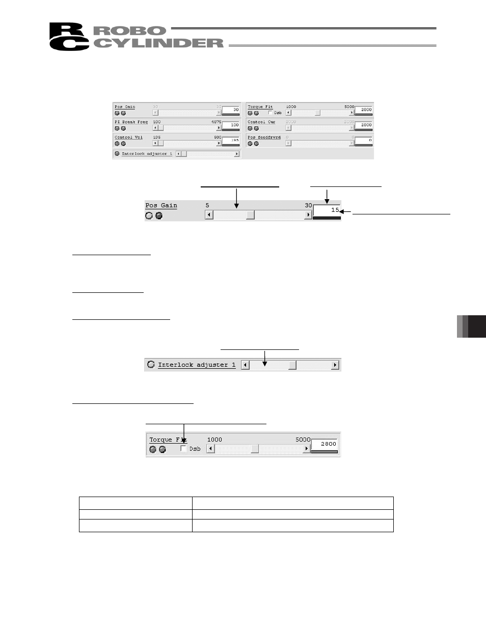
[3] Adjustment Band Settings
Fig. 12.37 Adjustment Band Settings
Fig. 12.38 Adjustment Band Settings (Pos Gain)
Band setting scroll bar
By operating this scroll bar, the band setting of the switch can be changed.
(Note) The operation is available only on the switches that are available for adjustment only.
Band setting display
In here, displays the current band setting.
Band setting degree display
In here, displays the degree of the current band setting. The gauge changes in the order of blue light
blue yellow red. Higher the setting gets, the closer the color of the gauge comes to red.
Fig. 12.39 Interlock adjuster Band Setting
Torque filter bandwidth inactivated (Version V9.02.00.00 or later)
Fig. 12.40 Torque filter bandwidth inactivated
The settings are as shown below for when there is a tick in the checkbox for the torque filter bandwidth
inactivated and there is no check.
Check
Adjustment Gain Torque Filter Time Constant
When there is a tick (3)
0
When there is no tick (blank)
Value calculated from torque filter bandwidth setting
(Note) Even when there is a tick in the checkbox, changes can be made in the torque filter bandwidth
itself and the setting in the torque filter bandwidth by the interlocking adjuster.
(Note) When the manual adjustment window is shown from the adjustment method select window, and
when the torque filter constant in the adjustment gain is 0, the tick in the checkbox is kept (3).
Band setting scroll bar
Band setting display
Band setting degree display
Band setting scroll bar
Torque filter bandwidth inactivated