IAI America RCM-101-USB User Manual
Page 67
5. Editing Position Data on CON Controllers and Older Models
55
(7) Position data input area: PCON, ACON, SCON-C, SCON-CA, ERC2, ERC3, ROBONET
and MSCON
Input the position data.
It is normally possible to input five items of Position, Speed, Acceleration (ACC), Deceleration (DCL) and
Comment, however, it becomes further possible to input items of Push, Threshold (LoTh), Positioning Band,
Zone+, Zone-, Acceleration and deceleration (Acc/Dcl) mode, Incremental (ABS/INC), Command (Cmnd)
mode and Stop mode by switching to detailed indication with the Indication switching button
.
In Version V8.03.00.00, “Command Mode” changes to “Gain Set” and “Vib. Sup. No.” is also added. (Refer to
(8), “Position data input area: SCON-CA, PCON-CA, ERC3 and MSCON.”)
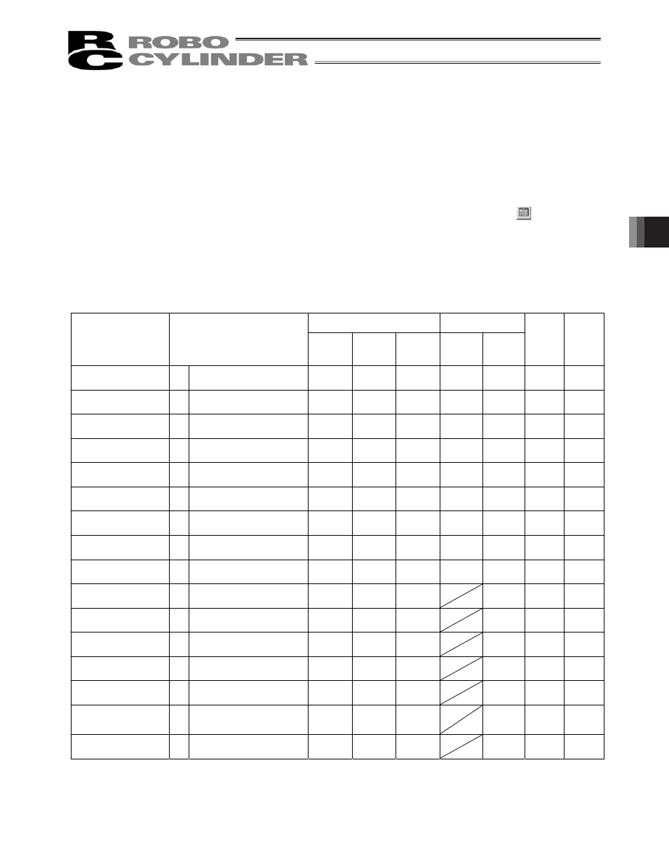
As shown in the table, the zone+, zone-, acceleration and deceleration mode, stop mode are enabled or
disabled depending on the type of controller.
List of ON/OFF of Position Table According to Model
AccDcl Mode
Stop Mode
Position Table
Zone +/-
Trapezoid
S-shape
First-order
Delay
Full Servo
Auto
Servo
OFF
Gain Set Vib. Sup.
No.
ERC2
{
PIO pattern: 3
{
Ч
Ч
{
{
Ч
Ч
ERC2-SE
{
-
{
Ч
Ч
{
Ч
Ч
Ч
ERC3
{
PIO pattern: 3
{
{
{
{
{
Ч
Ч
ERC3 PIO Converter
{
PIO pattern: 0, 1, 2, 4, 5
{
{
{
{
{
Ч
Ч
PCON-C/CG/CF
{
PIO pattern: 0, 1, 2, 4, 5
{
Ч
Ч
{
{
Ч
Ч
PCON-CA
{
PIO pattern: 0, 1, 2, 4, 5
{
{
{
{
{
Ч
Ч
-CY
{
PIO pattern: 1
{
Ч
Ч
{
{
Ч
Ч
-SE
{
-
{
Ч
Ч
{
Ч
Ч
Ч
RPCON
{
PIO pattern: 0, 1, 2, 4, 5
{
Ч
Ч
{
Ч
Ч
Ч
ACON-C/CG
{
PIO pattern: 0, 1, 2, 4, 5
{
{
{
{
Ч
Ч
-CY
{
PIO pattern: 1
{
{
{
{
Ч
Ч
-SE
{
-
{
{
{
Ч
Ч
Ч
RACON
{
PIO pattern: 0, 1, 2, 4, 5
{
{
{
Ч
Ч
Ч
SCON-C positioner
{
PIO pattern: 0, 1, 2, 4, 5
{
{
{
{
Ч
Ч
SCON-CA positioner
{
PIO pattern: 0, 1, 2, 4, 5,
6, 7
{
{
{
{
{
{
MSCON
{
-
{
{
{
{
{
{