Operation pattern – IAI America RCM-101-USB User Manual
Page 88
6. Initial Setting and Position Data Editing for SEP
Controllers
76
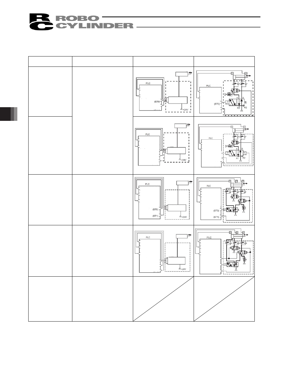
Operation pattern
Equivalent air cylinder circuits are shown for your reference.
Operation pattern
Description
Motorized cylinder connection
method
Air cylinder circuit (reference)
PIO pattern 2
Single solenoid type
(Movement between two
points)
(Position data change)
PIO pattern 2
Double solenoid type
(Movement between two
points)
(Position data change)
The actuator can be moved
between two points using the
same control you normally use
with an air cylinder.
You can switch between
positioning operation and
push-motion operation during
operation.
The target position (forward end,
backward end) can be set.
The travel speed and
acceleration/deceleration can be
specified.
Push-motion operation can also
be performed.
PIO pattern 3
Single solenoid type
(Movement by 2 inputs
among 3 points)
The actuator can be moved
among three points using the
same control you normally use
with an air cylinder.
The target position (forward end,
backward end) can be set.
The travel speed and
acceleration/deceleration can be
specified.
Push-motion operation can also
be performed.
PIO pattern 4
Double solenoid type
(Movement by 3 inputs
among 3 points)
The actuator can be moved
among three points using the
same control you normally use
with an air cylinder.
The target position (forward end,
backward end) can be set.
The travel speed and
acceleration/deceleration can be
specified.
Push-motion operation can also
be performed.
PIO pattern 5
(Continuous
back-and-forth
operation)
The actuator moves back and forth
between the two points of forward
end and backward end.
The target position (forward end,
backward end) can be set.
The travel speed and
acceleration/deceleration can be
specified.
Push-motion operation can also
be performed.
(Note) The air cylinder circuits are drawn with signal symbols corresponding to those used by ASEP,
PSEP, DSEP and MSEP controllers.
For details on signal symbols, refer to “ASEP/PSEP/DSEP Operation Manual” and “MSEP
Operation Manual”.
Backward end
position detection
signal (LS0)
Forward end position
detection signal (LS1)
Movement signal
Target position
switching signal (CN1)
Air cylinder
P (Air)
P (Air)
Backward end
position detection
signal (LS0)
Forward end position
detection signal (LS1)
Forward end
movement signal (ST1)
Backward end
movement signal (ST0)
Target position
switching signal (CN1)
Air cylinder
P (Air)
P (Air)
Backward end position
detection signal (LS0)
Forward end position
detection signal (LS1)
Midway position
detection signal (LS2)
Movement signal 1
Movement signal 2
Air cylinder
Air cylinder
P (Air)
P (Air)
P (Air)
P (Air)
P (Air)
P (Air)
Backward end position
detection signal (LS0)
Forward end position
detection signal (LS1)
Midway position
detection signal (LS2)
Midway point movement
signal (ST2)
Forward end movement
signal (ST1)
Backward end
movement signal (ST0)
Backward end
position detection
signal (LS0)
Forward end position
detection signal (LS1)
Movement signal
Motorized cylinder
Dedicated
cable
Target position
switching signal (CN1)
ASEP,
PSEP,
DSEP,
MSEP
Backward end
position detection
signal (LS0)
Forward end position
detection signal (LS1)
Forward end
movement signal (ST1)
Backward end
movement signal (ST0)
Motorized cylinder
Dedicated
cable
Target position
switching signal (CN1)
ASEP,
PSEP,
DSEP,
MSEP
Backward end position
detection signal (LS0)
Forward end position
detection signal (LS1)
Midway position
detection signal (LS2)
Movement signal 1
Movement signal 2
Motorized cylinder
Dedicated
cable
ASEP,
PSEP,
DSEP,
MSEP
Motorized cylinder
Dedicated
cable
Backward end position
detection signal (LS0)
Forward end position
detection signal (LS1)
Midway position
detection signal (LS2)
Midway point
movement signal (ST2)
Forward end
movement signal (ST1)
Backward end
movement signal (ST0)
ASEP,
PSEP,
DSEP,
MSEP