3 configuration utility menu screens, 1 user input keys, Configuration utility menu screens – Avago Technologies LSI SAS 3041E-R User Manual
Page 206: User input keys, Section 10.3, “configuration utility menu screens
10-4
Fibre Channel BIOS and Configuration Utility
Version 1.3
Copyright © 2001, 2002, 2007 by LSI Logic Corporation. All rights reserved.
Note:
Some devices detected by the Configuration Utility cannot
be controlled by the BIOS. Devices such as tape drives and
scanners require a device driver specific to that device. The
CU can be used to modify parameters for these devices.
10.3 Configuration Utility Menu Screens
All FC BIOS Configuration Utility menu screens are partitioned into the
following areas, starting at the top of the screen:
•
Header Area: This area lists static information text, including the
product title and version.
•
Menu Area: This area lists the current screen title and controller
information. It provides a cursor for selecting bracketed menu
options, such as
•
Main Area: This is the area for presenting data. This area has a
cursor for item selection, horizontal scrolling, and vertical scrolling.
Horizontal and vertical scroll bars appear here, if needed.
•
Footer Area: This area provides general help information text.
10.3.1 User Input Keys
The general key inputs listed in
are used for all menu screens
of the FC BIOS CU.
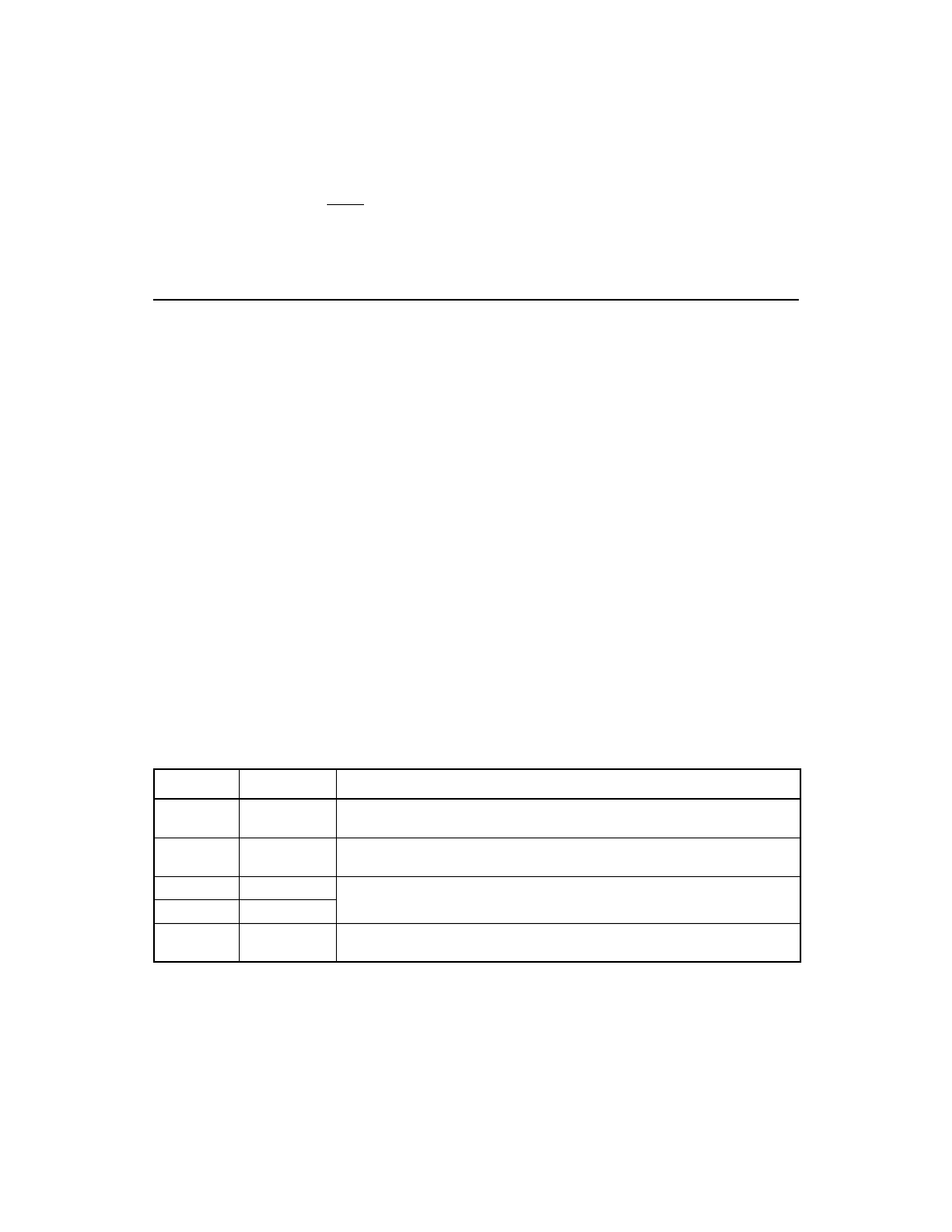
Table 10.1
User Input Keys
Key
Definition
Description
F1
Help
Displays context sensitive help for the field in which the cursor is
positioned.
F2
Menu
Moves the cursor to the menu selection area, where you can highlight a
menu item and press Enter to select it.
Arrow Keys
Select Item
Up, down, left, right movement to position the cursor.
Home/End
Select Item
+/-
Change Item
Items with values in brackets are modifiable. Use the numeric keypad ‘+’
and ‘-’ to change a modifiable field to its next relative value.
- LSI SAS 3041X-R LSI SAS 3080X-R LSI SAS 3081E-R LSI SAS 31601E LSI SAS 3442E-R FusionMPT_DevMgrUG.pdf LSI SAS 3442X-R LSI SAS 3800X LSI SAS 3801E LSI SAS 3801X LSI SAS 3041X-R (Channel) LSI SAS 3080X-R (Channel) LSI SAS 3081E-R (Channel) LSI SAS 3442E-R (Channel) LSI SAS 3442X-R (Channel) LSI SAS 3800X (Channel) LSI SAS 3801E (Channel) LSI SAS 3801X (Channel) LSI20160 LSI20160 (Channel) LSI20320 LSI20320-R LSI20320-R (Channel) LSI20320IE LSI20320IE (Channel) LSI21320-R LSI21320-R (Channel) LSI22320-R LSI22320-R (Channel) LSI22320SE LSI22320SE (Channel) LSIU320 LSIU320 (Channel) LSI53C1020