Grounding, Connections – Rockwell Automation 1503VC IntelliVAC Plus Contactor Control Module User Manual
Page 77
5-2
IntelliVAC Plus Basic Wiring
1503-UM054C-EN-P – June 2013
Grounding
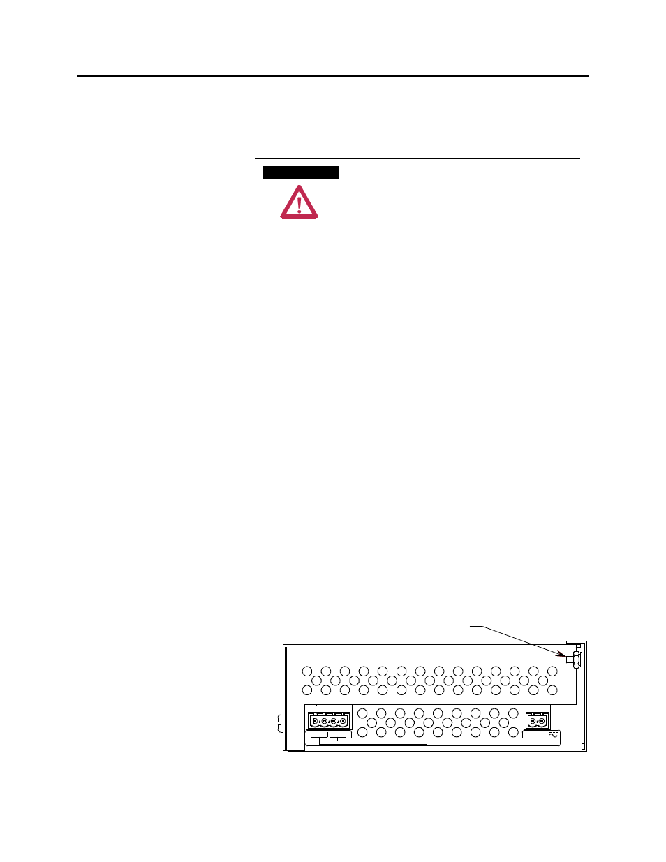
The IntelliVAC module must be connected to a common ground
terminal (PE) on the controller panel. The ground terminal is located
on the bottom of module enclosure (refer to Figure 5.1).
A T T E N T I O N
A T T E N T I O N
It is important that IntelliVAC is properly
grounded using the ground connection
provided. Failure to do so may result in
damage to equipment or personal injury.
Connections
There are five green connectors on the IntelliVAC Plus module for
connections to the control circuitry. Connector plugs are provided
with the module. If additional plugs are required, refer to Appendix
D, Spare parts.
Control Power
The IntelliVAC can accept either AC or DC control power. Refer to
Table 1.B for acceptable input power and control signal ratings.
Control power is applied to the module with a two-pole connector
located at the bottom rear portion of the module. Refer to Figure 5.1
for connections. The ‘L1’ connection is intended to be the ‘Hot’ or
‘+’ side of the control power, and the ‘L2/N’ connection is intended
to be the ‘Neutral’, ‘Return’, or ‘-’ side of the control power.
Status Relays
Status relay connections are accessed with a four-pole connector
located at the bottom front portion of the module. Refer to Figure
5.1 for connections. There are two status relays, each with one
normally-open contact:
Module Status:
Terminals 13 and 14
Contactor Status: Terminals 15 and 16
L2/N
L1
CONTACTOR STATUS OUTPUT (N.O.)
MODULE STATUS OUTPUT (N.O.)
POWER INPUT
13 14 15 16
Ground Connection
Figure 5.1 – IntelliVAC Base Bottom Side Connections