Rockwell Automation 1503VC IntelliVAC Plus Contactor Control Module User Manual
Page 168
Troubleshooting 10-5
1503-UM054C-EN-P – June 2013
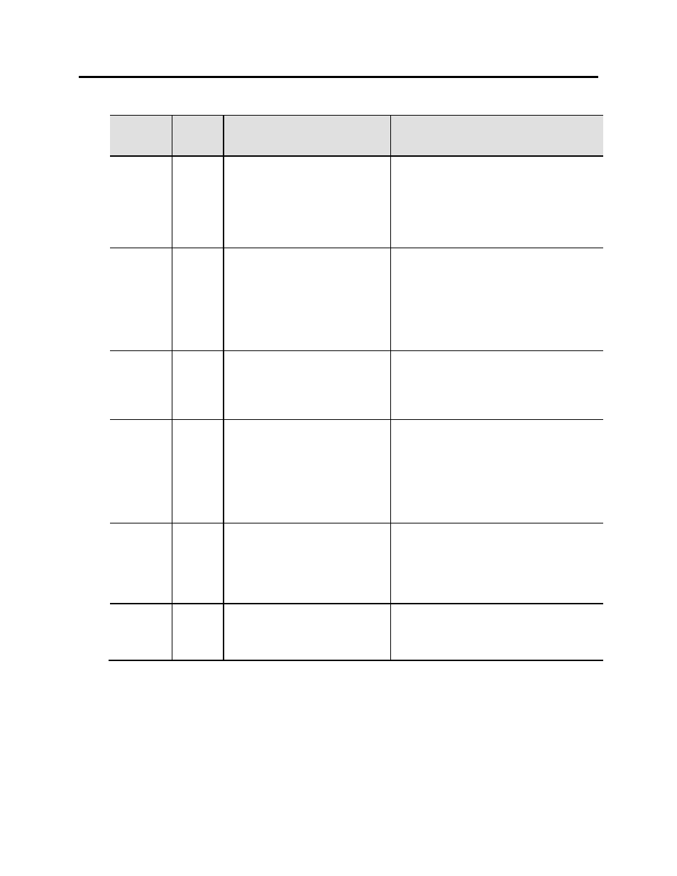
Table 10.B - IE Operations Troubleshooting Procedures (cont.)
Plus Status
LED Color
State
Condition/Possible Cause
Corrective Action
Green
2 pulses
Warning
RTC failure
RTC not responding
1. Replace the IntelliVAC Plus module.
Green
3 pulses
Warning
Line undervoltage
Input mains voltage is too low
Input mains voltage is too low on other
MC units
Check the mains input line and verify that it remains
greater than 95Vrms to allow a contactor to be
closed. If the input voltage remains less than 95Vrms
then improvements to the source must be made.
This warning can be from any of the IntelliVAC MC
units in an MC system. Perform the same checks for
those units as well.
Green
4 pulses
Warning
Line overvoltage
Input mains voltage is too high
Input mains voltage is too high on other
MC units
Check the mains input line and verify that it remains
lower than 265Vrms to prevent damage to the
IntelliVAC Plus module.
This warning can be from any of the IntelliVAC MC
units in an MC system. Perform the same checks for
those units as well.
Green
5 pulses
Warning
Extended close time
Faulty contactor mechanics
Faulty contactor coil
Faulty contactor coil on other MC units
Check the mechanical condition of the contactor as
this warning is an indication that the moving
mechanisms of the contactor are beginning to wear.
Check the resistance of the contactor coil and
compare it to the values.
This warning can be from any of the IntelliVAC MC
units in an MC system. Perform the same checks for
those units as well.
Green
6 pulses
Warning
DeviceNet power loss
1. DeviceNet connection faulty
2. DeviceNet input voltage too low
Check that the DeviceNet connections to the
IntelliVAC Plus are correct and that the DeviceNet
source connections are correct as well.
Check that the DeviceNet input voltage at terminals
TB1-5,1 is greater than the minimum voltage as
defined in the Electrical Specification
Green
7 pulses
Warning
MC Altitude setting
Incorrect altitude DIP switch setting
The altitude setting defined by the DIP switches
(SW1-1,2,3) on the Basic module is not consistently
set on all units in an MC system. Adjust the DIP
switches on all units to the same altitude setting.