Appendix c_maintenance, Appendix, Maintenance – Rockwell Automation 1503VC IntelliVAC Plus Contactor Control Module User Manual
Page 362
Appendix
C
1503-UM054C-EN-P – June 2013
Maintenance
Introduction
The IntelliVAC Plus product has is a very robust device which
contains only two user serviceable parts. These parts are:
the fuse for the mains input line and
the battery used by the Real Time Clock (RTC) circuitry.
Mains Input Fuse
This fuse is designed to protect the IntelliVAC Plus unit in the event
of the failure of a contactor coil or failure of an internal electronic
component. If power is applied to the mains input at TB1-2 and the
unit does not respond then the problem may be that the input fuse has
failed.
I M P O R T A N T
I M P O R T A N T
A properly grounded anti-static strap should
be used at this point.
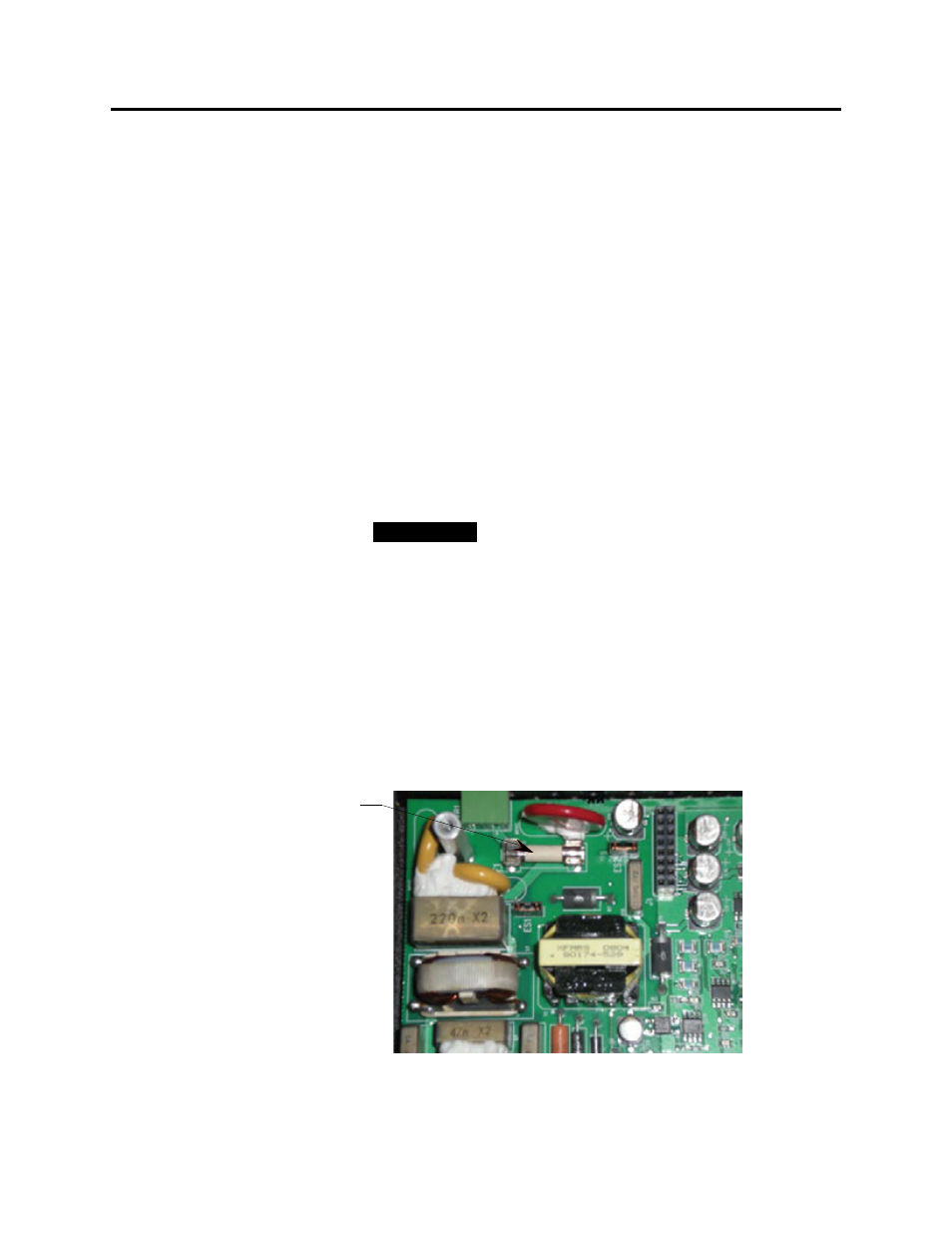
Begin by removing power to the IntelliVAC unit. To change the
fuse (see Fig C.1 below), remove the two screws on the front of the
case and then remove the front section of the enclosure. Next,
remove the three screws that hold the IE circuit board to the IB
circuit board. Carefully remove the IE circuit board (note that there
is a 16 pin connector between the two boards) and place it on a static
free surface. Now remove the fuse on the lower right side of the IB
module and replace it with a new fuse (see Spare Parts list in
Appendix C).
Fuse
Figure C.1 – Fuse Location