Allied Telesis AlliedView-EMS 4.0.1 DEVICE MANAGEMENT User Manual
Page 334
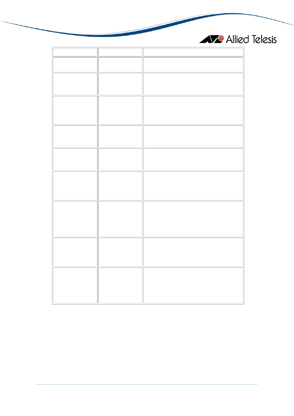
Left Bay
Right Bay
Numbering
None
None
1 to 25 (Port 25 is invalid and should be
ignored.)
None
AT-XEM-1XP
1 to 26 (Port 25 will not show any valid
data. Port 26 is invalid and should be
ignored.)
None AT-XEM-12S
AT-XEM-12T
1 to 37 (Ports 25 to 36 are invalid and
should be ignored. Port 37 will show
data for port 1 of the module on the
right bay.)
AT-XEM-1XP
None
1 to 26 (Port 25 will show data for the
port on the left bay. Port 26 is invalid
and should be ignored.)
AT-XEM-12S
AT-XEM-12T
None
1 to 37 (Ports 25 to 36 will show data
for ports on the left bay. Port 37 is
invalid and should be ignored.)
AT-XEM-1XP AT-XEM-1XP 1
to
27
(Port 25 will show data for the
port on the left bay. Port 26 will not
show any valid data. Port 27 is invalid
and should be ignored.)
AT-XEM-1XP AT-XEM-12S
AT-XEM-12T
1 to 38 (Port 25 will show data for the
port on the left bay. Ports 26 to 36 will
not show any valid data. Ports 37 and 38
will show data for ports 1 and 2 of the
module on the right bay.)
AT-XEM-12S
AT-XEM-12T
AT-XEM-1XP
1 to 38 (Ports 25 to 36 will show data
for ports on the left bay. Port 37 will
show data for the port on the right bay.
Port 38 is invalid and should be ignored.)
AT-XEM-12S
AT-XEM-12T
AT-XEM-12S
AT-XEM-12T
1 to 49 (Ports 25 to 36 will show data
for ports on the left bay. Ports 37 to 48
will show data for ports on the right
bay. Port 49 is invalid and should be
ignored.)
Bandwidth Limits
Displays bandwidth limits of the switch ports.
Note
- The current firmware version does not allow the Ingress Limit parameter to
be configured.
Error Statistics
Displays error statistics.
AlliedView™-EMS 4.0.1 Device Management Guide
Page 334 of 411