Allied Telesis AlliedView-EMS 4.0.1 DEVICE MANAGEMENT User Manual
Page 283
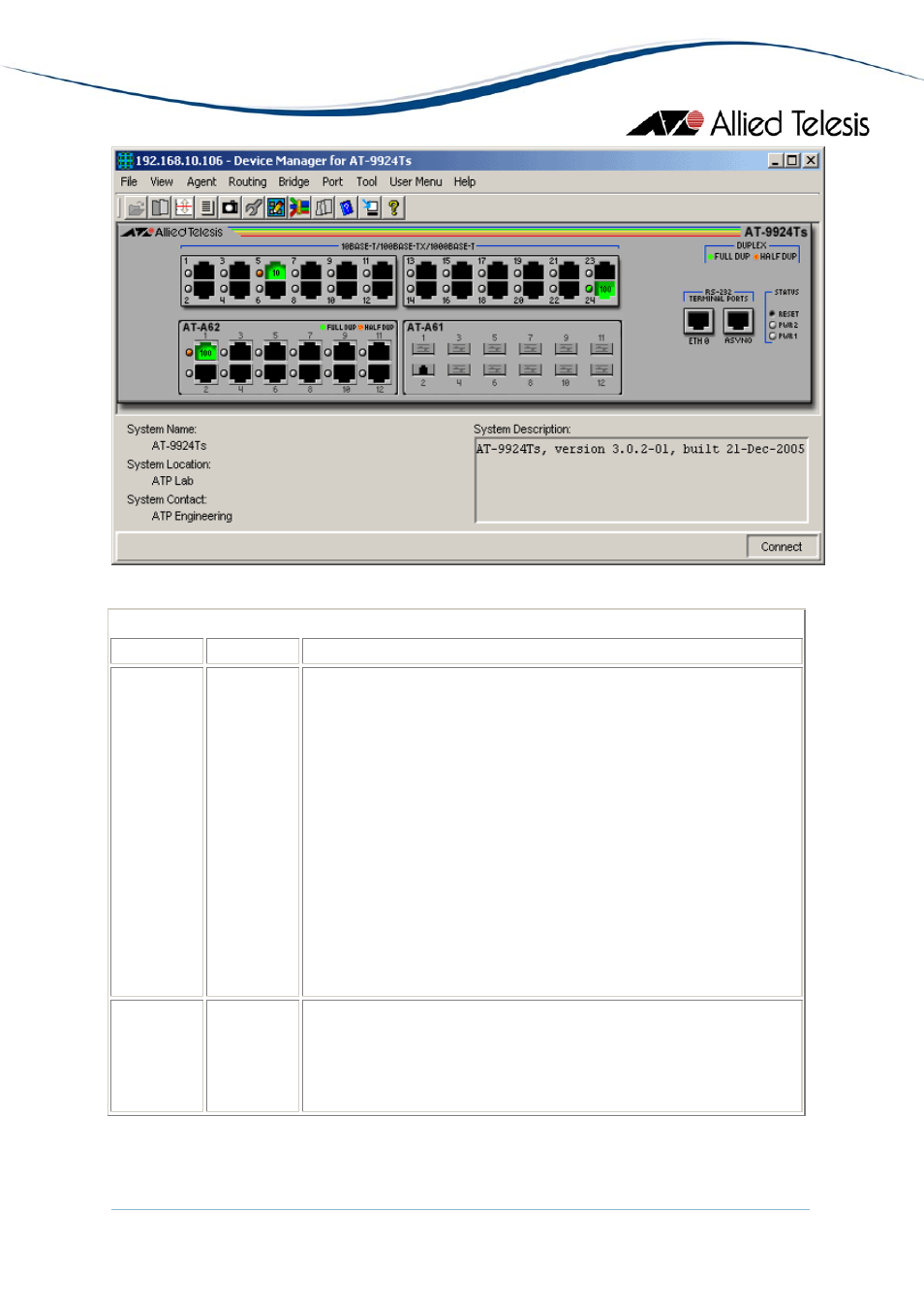
AT-9924Ts
Device Manager LEDs for AT-9900/AT-9900s Series
LED
State
Description
PWR 1 and
PWR 2
Green
Gray
Red
There is a power supply unit (PSU) in the PSU bay, and it is
supplying power to the switch.
There is a functioning Fan Only Module (FOM) in the PSU bay.
Either:
- there is no PSU or FOM in the PSU bay, or
- a PSU is installed but has a power supply or fan fault, or its
temperature has exceeded its recommended threshold, or
- an FOM is installed and a fan has failed.
Note
- No FOM is OK for AT-9924T and AT-9924SP.
DUPLEX Green
Orange
Gray
The port is operating at full duplex.
The port is operating at half duplex.
The port has no link.
Note
- Please refer to Uplink Modules for the operations and behavior of the Expansion
Modules installed on these devices.
AlliedView™-EMS 4.0.1 Device Management Guide
Page 283 of 411
- AT-GS908M (54 pages)
- AT-x230-10GP (80 pages)
- AT-GS950/10PS (386 pages)
- AT-GS950/48PS (64 pages)
- AT-GS950/16PS (386 pages)
- AT-GS950/48PS (386 pages)
- AT-9000 Series (1480 pages)
- AT-9000 Series (258 pages)
- IE200 Series (70 pages)
- AT-GS950/48 (410 pages)
- AT-GS950/8 (52 pages)
- AT-GS950/48 (378 pages)
- AT-GS950/48 (60 pages)
- SwitchBlade x8106 (322 pages)
- SwitchBlade x8112 (322 pages)
- SwitchBlade x8106 (240 pages)
- SwitchBlade x8112 (240 pages)
- AT-TQ Series (172 pages)
- AlliedWare Plus Operating System Version 5.4.4C (x310-26FT,x310-26FP,x310-50FT,x310-50FP) (2220 pages)
- FS970M Series (106 pages)
- 8100L Series (116 pages)
- 8100S Series (140 pages)
- x310 Series (120 pages)
- x310 Series (116 pages)
- AT-GS950/24 (404 pages)
- AT-GS950/24 (366 pages)
- AT-GS950/16 (44 pages)
- AT-GS950/16 (364 pages)
- AT-GS950/16 (404 pages)
- AT-GS950/8 (404 pages)
- AT-GS950/8 (364 pages)
- AT-GS950/8 (52 pages)
- AT-8100 Series (330 pages)
- AT-8100 Series (1962 pages)
- AT-FS970M Series (330 pages)
- AT-FS970M Series (1938 pages)
- SwitchBlade x3106 (288 pages)
- SwitchBlade x3112 (294 pages)
- SwitchBlade x3106 (260 pages)
- SwitchBlade x3112 (222 pages)
- AT-S95 CLI (AT-8000GS Series) (397 pages)
- AT-S94 CLI (AT-8000S Series) (402 pages)
- AT-IMC1000T/SFP (23 pages)
- AT-IMC1000TP/SFP (24 pages)
- AT-SBx3106WMB (44 pages)