Allied Telesis AlliedView-EMS 4.0.1 DEVICE MANAGEMENT User Manual
Page 184
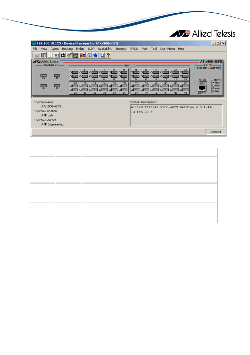
AT-x900-48FS
Device Manager LEDs for the AT-x900-48 Series
LED
State
Description
PWR 1 and
PWR 2
Green
Gray
There is a power supply unit (PSU) in the PSU bay.
There is no power supply unit (PSU) in the PSU bay.
FAN Green
Gray
There is a functioning Fan Only Module (FOM) in the PSU bay.
There is no functioning Fan Only Module (FOM) in the PSU bay.
DUPLEX Green
Orange
The port is operating at full duplex.
The port is operating at half duplex.
Note
- The current firmware version does not allow Device Manager to display the correct
image for SFP module 'AT-SPFXBD-LC-13'. As a result, the SFP image that will be displayed
is the generic SFP Fiber image.
Note
- When a single PSU is installed, it is advised to install it in the device's PSU Bay 2 in
order for the Device Manager to display correct information on the Fan and Power Supply
modules.
AlliedView™-EMS 4.0.1 Device Management Guide
Page 184 of 411
- AT-GS908M (54 pages)
- AT-x230-10GP (80 pages)
- AT-GS950/10PS (386 pages)
- AT-GS950/48PS (64 pages)
- AT-GS950/16PS (386 pages)
- AT-GS950/48PS (386 pages)
- AT-9000 Series (1480 pages)
- AT-9000 Series (258 pages)
- IE200 Series (70 pages)
- AT-GS950/48 (410 pages)
- AT-GS950/8 (52 pages)
- AT-GS950/48 (378 pages)
- AT-GS950/48 (60 pages)
- SwitchBlade x8106 (322 pages)
- SwitchBlade x8112 (322 pages)
- SwitchBlade x8106 (240 pages)
- SwitchBlade x8112 (240 pages)
- AT-TQ Series (172 pages)
- AlliedWare Plus Operating System Version 5.4.4C (x310-26FT,x310-26FP,x310-50FT,x310-50FP) (2220 pages)
- FS970M Series (106 pages)
- 8100L Series (116 pages)
- 8100S Series (140 pages)
- x310 Series (120 pages)
- x310 Series (116 pages)
- AT-GS950/24 (404 pages)
- AT-GS950/24 (366 pages)
- AT-GS950/16 (44 pages)
- AT-GS950/16 (364 pages)
- AT-GS950/16 (404 pages)
- AT-GS950/8 (404 pages)
- AT-GS950/8 (364 pages)
- AT-GS950/8 (52 pages)
- AT-8100 Series (330 pages)
- AT-8100 Series (1962 pages)
- AT-FS970M Series (330 pages)
- AT-FS970M Series (1938 pages)
- SwitchBlade x3106 (288 pages)
- SwitchBlade x3112 (294 pages)
- SwitchBlade x3106 (260 pages)
- SwitchBlade x3112 (222 pages)
- AT-S95 CLI (AT-8000GS Series) (397 pages)
- AT-S94 CLI (AT-8000S Series) (402 pages)
- AT-IMC1000T/SFP (23 pages)
- AT-IMC1000TP/SFP (24 pages)
- AT-SBx3106WMB (44 pages)