3 operation status – GW Instek APS-1102 User Manual User Manual
Page 219
6.5 Status System
APS-1102 Programmable AC/DC Power Source
6-47
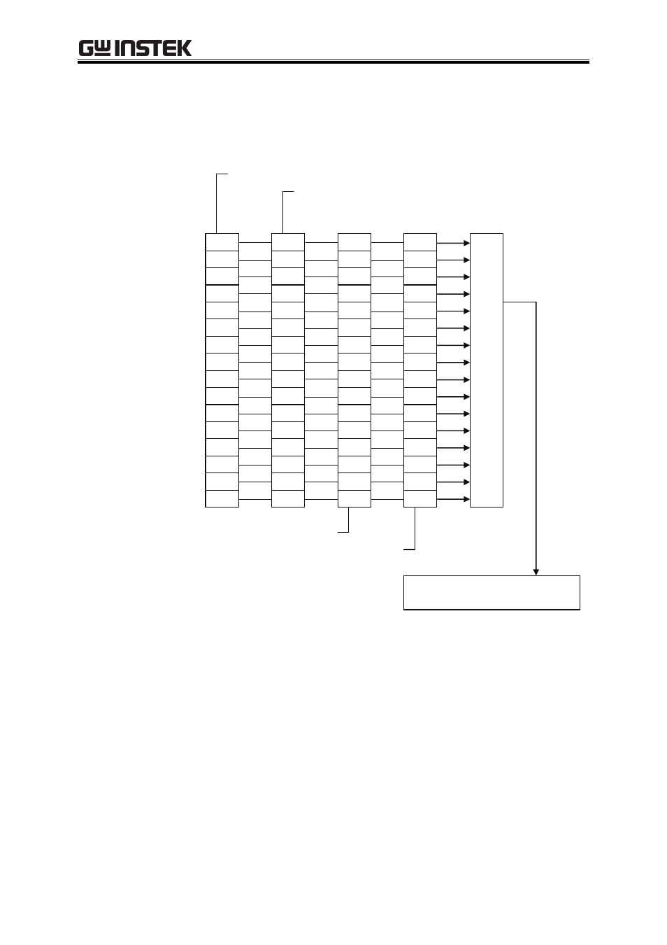
6.5.3 Operation status
The structure of the operation status register is shown in Figure 6-6 below.
Always 0
Under sequence execution
Not used
Under sequence hold
Not used
Not used
Not used
Not used
15
14
13
12
11
10
9
8
OPCR (operation condition register)
Logi
ca
l O
R
OPTF (operation transition filter)
Operation status summary
Status byte (bit 7)
7
6
5
4
3
2
1
0
Not used
Not used
Not used
Not used
Not used
Not used
BUSY
Not used
7
6
5
4
3
2
1
0
15
14
13
12
11
10
9
8
7
6
5
4
3
2
1
0
15
14
13
12
11
10
9
8
7
6
5
4
3
2
1
0
15
14
13
12
11
10
9
8
OPER (operation event register)
OPEE (operation event enable register)
Figure 6-6. Operation Status
The transition filters convert conditions to events.
The transition filters include an NTRansition filter and a PTRansition filter. The settings and operations
of these filters are described below.
When the NTR filter is set to 1, OPER is set to 1 when OPCR changes from 1 to 0.
When the PTR filter is set to 1, OPER is set to 1 when OPCR changes from 0 to 1.
When the NTR and PTR filters are both set to 1, OPER is set to 1 when OPCR changes.
When the NTR and PTR filters are both set to 0, changes in OPCR are not propagated to OPER.