Configuring pe2, Ieee 802.1ag with vll-local, Mpls configurations on pe1 – Brocade Multi-Service IronWare Administration Guide (Supporting R05.6.00) User Manual
Page 196
178
Multi-Service IronWare Administration Guide
53-1003028-02
CFM monitoring and show commands
6
Configuring PE2
1. To enable CFM, enter the following command.
PE2(config)#cfm-enable
2. Create a maintenance domain with a specified name PROVIDER_1 and level 4.
PE2config-cfm)#domain-name PROVIDER_1 level 4
3. Create a maintenance association within a specified domain of vll-id 30 with a priority 3.
PE1(config-cfm-md-PROVIDER_1)#ma-name ma_8 vll-id 30 priority 3
4. Set the time interval between successive Continuity Check Messages.The default is
10-seconds.
PE1(config-cfm-md-PROVIDER_1-ma-ma_8)#ccm-interval 10-second
5. Configure MEP 4 down on port 1/1 and vlan 30
CE-1 (config-cfm-md-CUST_2-ma-ma_6)#mep 4 down vlan 30 port ethe 1/1
To monitor the connectivity between PE-1 and PE-2, we could use “show cfm connectivity”
commands as mentioned in the previous scenario. Also we could use either loopback or
linktrace on PE-1 or PE-2.
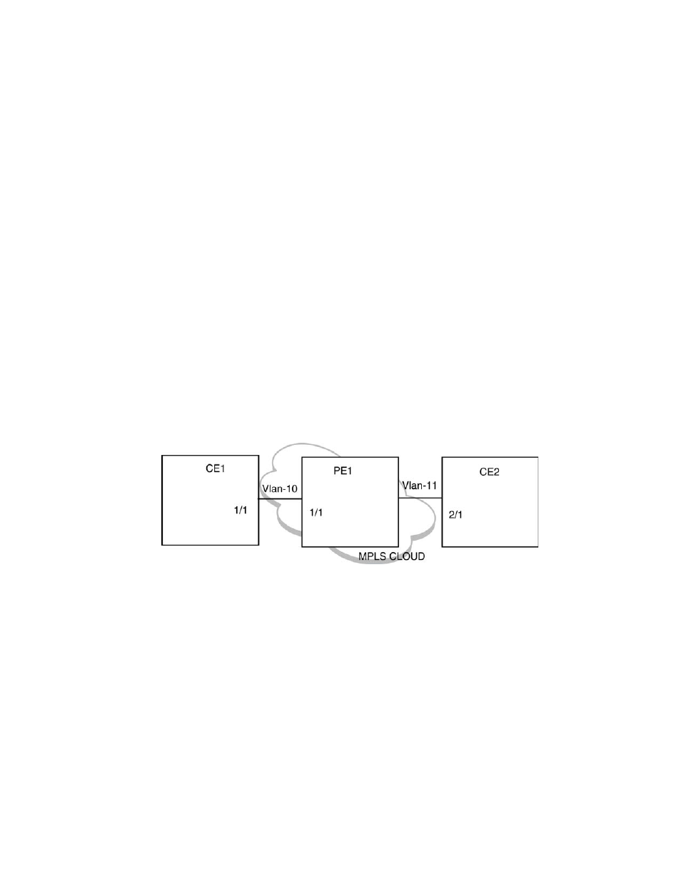
IEEE 802.1ag with VLL-LOCAL
FIGURE 11
IEEE 802.1ag over VLL-LOCAL
In the case of IEEE 802.1ag over VLL-LOCAL, the PE acts as a MIP and VLL does VLAN translation.
As shown in
. MEP is configured on vlan-10 on CE1 and vlan-11 on CE2. On PE1, MIP is
configured on VLL-LOCAL and which has vlan-10, port 1/1 and vlan-11,port 2/1 configured as end
points.
UP MEP would not be allowed for VLL-Local.
MPLS configurations on PE1
Before configuring CFM on PE1 we need to do MPLS Configuration on PE1.
Enter the following commands to configure VLL peers from PE1 to PE 2.
1. To create a VLL instance, enter commands such as the following.
PE1(config)#router mpls
PE1(config-mpls)vll-local test1
2. To specify an un-tagged endpoint for a VLL instance, enter the following commands.
PE1(config-mpls-vll-test1)untagged ethe 1/1