Connecting to the timer – Daktronics OmniSport 2000 Timing Console User Manual
Page 25
Timing System Setup
7
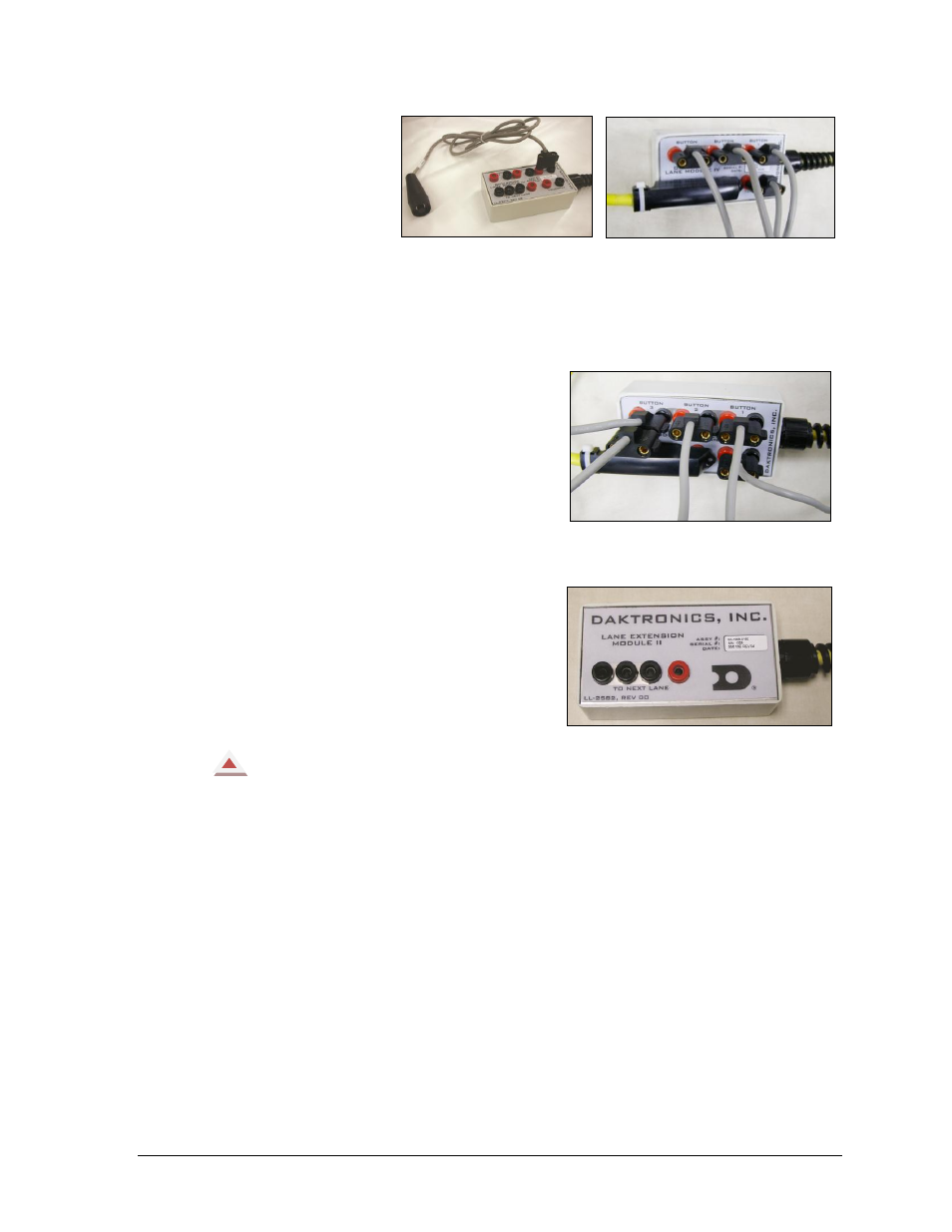
The push button
connection jacks
(marked Button 1,
Button 2 and
Button 3) accept
input from backup
buttons held by up
to three timing
judges per lane. As with the touchpad
connection, match the black jack with the GND side of the plugs (Figure 14).
If only one backup button is used, connect it to the jack marked Button 1.
Figure 15 illustrates a lane module with all the connections made except the RTOP.
The Relay Take-Off Platform connection
plugs into Button 3, again matching the
black jack with the GND side of the plug.
If the system is using all three buttons per
lane (Figure 16), the RTOP plug may be
piggy-backed to the push button plug using
Button 3. If the system is only using 1 or 2
buttons per lane, plug the banana connector
from the RTOP directly into Button 3. For
more information on the RTOP, refer to
Section 13.
The Lane Extension Module (Figure 17) is
an extension cable between the OmniSport
2000 console and the closest lane module.
Standard lengths of lane extension
available are 25', 50', 100', and 200'
(7.6 m, 15.2 m, 30.5 m, and 61 m).
Always Remember:
If some touchpads are connected backwards and some connected correctly, it will
cause touchpads to register times when the pad has not been touched.
Watch for poor connections between plugs and jacks on the lane module. Inspect
cabling and connectors for corrosion and damage. Use the silicone lubricant found in
the maintenance kit to protect the jacks and plugs from corrosion. Refer to Figure 12
on how to clean the plugs and use the silicone before and after each use.
Connecting to the Timer
Connect the four-pin plug from the deck extension from the “Near” end (or primary finish
end) into J10 or the Near Lane jack on the OmniSport 2000 console. If Far End (or split end)
touchpads are being used, connect the four-pin plug from that extension cable into J11 Far
Lane jack on the timing console. For more information on the OmniSport 2000 timer
connections, refer to Figure 28 in Section 2.7.
Figure 14: Push Button
Figure 15: Lane Module with All
Connections Except RTOP
Figure 16: RTOP Connected Piggy-back
Style on Button 3
Figure 17: Lane Extension Module